A/D-D/A Converter Circuit
A_D_converter_for_3_digit_LED_display
Published:2009/7/24 10:01:00 Author:Jessie | From:SeekIC
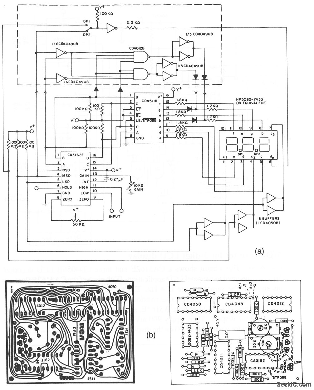
This circuit shows a CA3162A connected to a CD4511B decoder/driver to operate a common-cathode LED display. Figure 6-21B shows the PC tenmplate and component layout. The additional logic shown within the dotted area allows the display of negative numbers as low (as -99 mV), depending on the Position of the DP1/DP2 switch. The sampling rate can be changed from 4 to 96 Hz when pin 6 of'the CA3162A is connected to +5 V. To adjust, follow the proccdure described for Fig. 6-20. Harris Semiconductors, Data Acquisition, 1991, p. 2-6, 2-7.
Reprinted Url Of This Article:
http://www.seekic.com/circuit_diagram/A-D_D-A_Converter_Circuit/A_D_converter_for_3_digit_LED_display.html
Print this Page | Comments | Reading(3)

Article Categories
power supply circuit
Amplifier Circuit
Basic Circuit
LED and Light Circuit
Sensor Circuit
Signal Processing
Electrical Equipment Circuit
Control Circuit
Remote Control Circuit
A/D-D/A Converter Circuit
Audio Circuit
Measuring and Test Circuit
Communication Circuit
Computer-Related Circuit
555 Circuit
Automotive Circuit
Repairing Circuit
Code: