555 Circuit
The automatical overcurrent protection circuit of 555 motor
Published:2011/6/10 20:06:00 Author:nelly | Keyword: overcurrent protection, motor | From:SeekIC

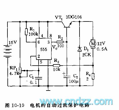
As shown in the figure 10-10, the overcurrent protection circuit is made as the core of 555 which is connected into R-S trigger pattern. In the figure, M is DC motor which is needed to limit current or regulate speed. 555's 6 foot(R terminal)connects high level, 2 foot(S terminal)is connected between M and sample resistor R4. RP1 is used to adjust the control terminal's(5 foot)voltage, namely, adjusting R terminal's and S terminal's threshold voltages. When it works normally, adjusting RP1, R4's sample voltage is lower than S terminal's threshold level, 555 is set, VT1 is saturation conduction, M operates normally.
Reprinted Url Of This Article:
http://www.seekic.com/circuit_diagram/555_Circuit/The_automatical_overcurrent_protection_circuit_of_555_motor.html
Print this Page | Comments | Reading(3)

Article Categories
power supply circuit
Amplifier Circuit
Basic Circuit
LED and Light Circuit
Sensor Circuit
Signal Processing
Electrical Equipment Circuit
Control Circuit
Remote Control Circuit
A/D-D/A Converter Circuit
Audio Circuit
Measuring and Test Circuit
Communication Circuit
Computer-Related Circuit
555 Circuit
Automotive Circuit
Repairing Circuit
Code: