555 Circuit
Operation principle of 555 estable multi-vibrator model
Published:2011/7/30 3:06:00 Author:Zoey | Keyword: 555, Astable Multi-vibrator, Model | From:SeekIC


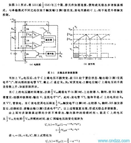
As shown in the picture 3-1, an astable multi-vibrator can be formed after connecting a 555, three resistances and a capacity accessory, the trigger (pin 2) is connected on loop C.
When galvanized voltage VDD, 555 will be reset and pin 3 will havehigh level “1”, the discharge tube VT1 will cease to discharge, and C will get charged via Ra and Rb.
Voltage on C increases along with time, when it gets 2/3 VDD threshold value level, the upper comparator A1 will turn over, RS trigger willset and output a low level”0”, at that time, the discharge tube VT1 will be saturated and conducted, electric charge on C will discharge through Rb to VT1. When C discharges to 1/3 VDD, the upper comparator A2 will turn over, RS trigger willreset and output a high level”1”, this process will be repeated many times.
By analyzing the results, we can conclude that the change rule of voltage on the two terminals of C can be formulated as follow:
Uc(t)=VDD(1-e-t(RA+RB)C)
+1/3 VDDE-t(RA+RB)C
If we replace (RA+RB) with t1, the formula can be simplified as follow:
Uc(t)=VDD(1-2/3•e-t/t1)
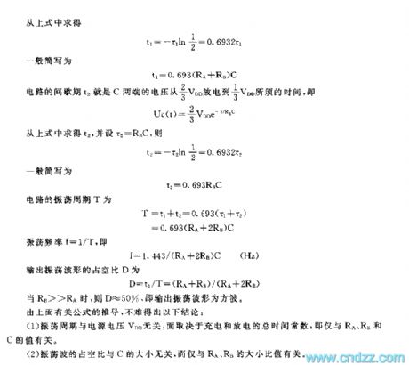
Following formula can be concluded:
T=0.693(RA+2RB)C
D=t1/T=(RA+RB)/(RA+2RB)
If RA>>RB, then D≈50%, the output oscillation wave is square wave.
finally we can draw following conclusions:
(1) The oscillation period is not relevant to VDD, but is determined by charge and discharge time constant, that is, the value of RA, RB, and C
(2) Duty cycle of the oscillation is not relevant to C , but is relevant to the ratio of RA and RB
Reprinted Url Of This Article:
http://www.seekic.com/circuit_diagram/555_Circuit/Operation_principle_of_555_estable_multi_vibrator_model.html
Print this Page | Comments | Reading(3)

Article Categories
power supply circuit
Amplifier Circuit
Basic Circuit
LED and Light Circuit
Sensor Circuit
Signal Processing
Electrical Equipment Circuit
Control Circuit
Remote Control Circuit
A/D-D/A Converter Circuit
Audio Circuit
Measuring and Test Circuit
Communication Circuit
Computer-Related Circuit
555 Circuit
Automotive Circuit
Repairing Circuit
Code: