555 Circuit
Four Basic Circuits of 555 Monostable Trigger
Published:2011/7/5 Author:Zoey | Keyword: Basic Circuits, 555 Monostable Trigger | From:SeekIC

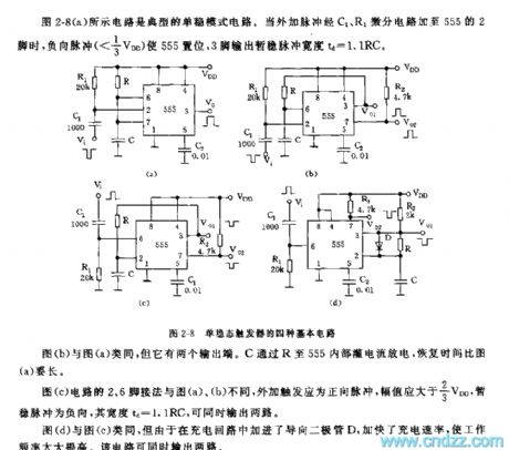
The circuit in the picture 2-8(a) is a typical monostable circuit. When external pulse is added to pin 2 of 555 via differential circuit C1 and R1, positive pulse will force 555 to set, temporarily stable pulse width that pin 3 outputs td is 1.1 RC.
Circuit in picture (b) has two output terminals. C discharges through R, and it takes longer for it to recover than that of (a).
Pin 2 and 6 in circuit of picture (c) joint a positive pulse, temporarily stable pulse is negative and the width is 1.1RC. They can output two circuits simultaneously.
Circuit in picture (d) has a faster charge ratio and higher work efficiency and can output two circuits simultaneously
Reprinted Url Of This Article:
http://www.seekic.com/circuit_diagram/555_Circuit/Four_Basic_Circuits_of_555_Monostable_Trigger.html
Print this Page | Comments | Reading(3)

Article Categories
power supply circuit
Amplifier Circuit
Basic Circuit
LED and Light Circuit
Sensor Circuit
Signal Processing
Electrical Equipment Circuit
Control Circuit
Remote Control Circuit
A/D-D/A Converter Circuit
Audio Circuit
Measuring and Test Circuit
Communication Circuit
Computer-Related Circuit
555 Circuit
Automotive Circuit
Repairing Circuit
Code: