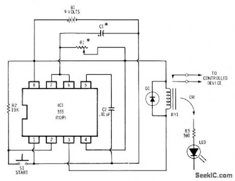
555 Circuit
BASIC_555_TIMER
Published:2009/7/13 4:17:00 Author:May | From:SeekIC

Closing switch S1 momentarily applies activating signal to trigger input pin 2 of timer, to start charging of C1. When C1 charges to two-thirds of supply voltage, timer discharges it to complete timing cycle. Duration of charging interval can be varied from several microseconds to over 5 min by changing values of R1 and C1. With 1K for R1, capacitor values of 0.01 to 100 μF give time range of 10μs to 100 ms. With 100 megohmsand lμF,time increases to 10s. Once timer starts, closing S1 again has no effect. Timing cycle can be interrupted only by applying reset pulse to pin 4 or opening power supply. Circuit will drive LED directly or can be used with miniature relay (Radio Shack 275-004) to control larger loads. Can be used as darkroom timer if LED is kept several feet away from photographic paper. Diode is 1N914.-F.M, Mims, Integrated Circuit Projects, Vol. 2, Radio Shack, Fort Worth, TX, 1977, 2nd Ed., p 57-65.
Reprinted Url Of This Article:
http://www.seekic.com/circuit_diagram/555_Circuit/BASIC_555_TIMER.html
Print this Page | Comments | Reading(3)

Article Categories
power supply circuit
Amplifier Circuit
Basic Circuit
LED and Light Circuit
Sensor Circuit
Signal Processing
Electrical Equipment Circuit
Control Circuit
Remote Control Circuit
A/D-D/A Converter Circuit
Audio Circuit
Measuring and Test Circuit
Communication Circuit
Computer-Related Circuit
555 Circuit
Automotive Circuit
Repairing Circuit
Code: