555 Circuit
555 pointer electronic megohmmeter
Published:2011/9/18 21:14:00 Author:Ecco | Keyword: 555 , pointer electronic megohmmeter | From:SeekIC

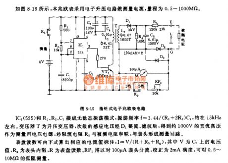
As shown in Figure 8-19, the megohmmeter uses the electronic boost circuit as measuring power, the range is 0.5 ~ 1000MΩ. IC1 and R1, R2, C1 are connected in non-steady-state oscillation mode, and the oscillation frequency f = 1.44 / (R1 +2 R2) C1, it is about 15kHz. Transformer T is the step-up transformer, the secondary induced voltage is rectified by D1, after being filtered, it can get 1000V DC high voltage power supply as measuring voltage, the current limiting resistor R5 and the measured resistor are connected in series and then form measuring loop with header. Dial readings can be calculated by the following formula, the current value of the corresponding label: I = V / (R + R5 + Rg), and V is the voltage on C5, Rg is the internal resistance of meter, R is the dial reading. RP1 header is used for for streaming on the 100μA header, correcting 2mA full-scale, and measuring low resistor with 0.5 ~ 10MΩ.
Reprinted Url Of This Article:
http://www.seekic.com/circuit_diagram/555_Circuit/555_pointer_electronic_megohmmeter.html
Print this Page | Comments | Reading(3)

Article Categories
power supply circuit
Amplifier Circuit
Basic Circuit
LED and Light Circuit
Sensor Circuit
Signal Processing
Electrical Equipment Circuit
Control Circuit
Remote Control Circuit
A/D-D/A Converter Circuit
Audio Circuit
Measuring and Test Circuit
Communication Circuit
Computer-Related Circuit
555 Circuit
Automotive Circuit
Repairing Circuit
Code: