555 Circuit
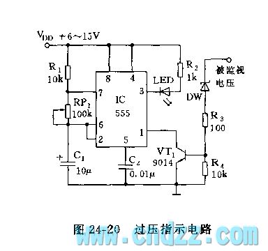
555 overvoltage indication circuit
Published:2012/10/16 21:54:00 Author:Ecco | Keyword: 555, overvoltage indication | From:SeekIC

As shown in Figure 24-10, 555, R1, RP1 and C1 form astable multivibrator, but its ground pin is connected to c pole of detection transistor. When the monitored voltage exceeds set value, DW is breakdown, VT1 is saturated and turned, then 555 starts oscillation, LED light flashes. VT1 can also reduce the static power dissipation of 555. 555 oscillation frequency can be adjusted between 1 ~ 20Hz, and RP1 can be used to select the flashing number of LED.
Reprinted Url Of This Article:
http://www.seekic.com/circuit_diagram/555_Circuit/555_overvoltage_indication_circuit.html
Print this Page | Comments | Reading(3)

Article Categories
power supply circuit
Amplifier Circuit
Basic Circuit
LED and Light Circuit
Sensor Circuit
Signal Processing
Electrical Equipment Circuit
Control Circuit
Remote Control Circuit
A/D-D/A Converter Circuit
Audio Circuit
Measuring and Test Circuit
Communication Circuit
Computer-Related Circuit
555 Circuit
Automotive Circuit
Repairing Circuit
Code: