555 Circuit
555 optical control delay flash toy car circuit
Published:2011/6/7 7:22:00 Author:nelly | Keyword: optical control, delay flash, toy car | From:SeekIC

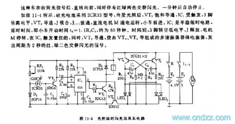
After receiving the optical signal, this car will move straight forward, at the same time, it has red and green alternately flashing. After one minute, it stops automatically.
As shown in the figure 11-4, silicon photocell adopts 2CR33 type, after illuminated, VT1 is saturation conduction, IC1 is triggered, 3 foot is high level, VT2 turns on, J pulls in, J1-1 turns on, DC motor M operates, the car moves. IC1 is monostable delay circuit, the delay time also is the car's running time td=1.1R4C3, it is about 60s. When it is time out, 3 foot turns to low level, J releases, motor M stops running. IC1 triggers setting, simultaneously, VT3 turns on, the multivibrator which is composed of VT4, VT5 starts to vibrate, it sends out the signal of red and green alternately flashing, the period is 2s.
Reprinted Url Of This Article:
http://www.seekic.com/circuit_diagram/555_Circuit/555_optical_control_delay_flash_toy_car_circuit.html
Print this Page | Comments | Reading(3)

Article Categories
power supply circuit
Amplifier Circuit
Basic Circuit
LED and Light Circuit
Sensor Circuit
Signal Processing
Electrical Equipment Circuit
Control Circuit
Remote Control Circuit
A/D-D/A Converter Circuit
Audio Circuit
Measuring and Test Circuit
Communication Circuit
Computer-Related Circuit
555 Circuit
Automotive Circuit
Repairing Circuit
Code: