555 Circuit
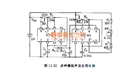
555 multi-analogue sound generator circuit
Published:2011/6/7 4:23:00 Author:nelly | Keyword: multi-analogue sound, generator | From:SeekIC

As shown in the figure 11-22, the circuit is composed of two 555 and some resistor capacitor components, the astable multivibrator connsists of IC1 and RP1, R1, C1, the oscillation frequency is about 5~10Hz, it can be changed by adjusting RP1. The frequency of oscillator which is made of IC2 and RP2, R2, C2 is between 1~10kHz, it can be changed by adjusting RP2, IC2 is a controlable voltage oscillator, its control terminal 5 foot is controlled by triangular wave voltage, this triangular wave is obtained from IC1 output and then integrated by R4, C3 integration circuit. IC2's oscillation frequency changes in relation to control voltage, it will send out all kinds of analogue sound, such as cricket noise and bird sound.
Reprinted Url Of This Article:
http://www.seekic.com/circuit_diagram/555_Circuit/555_multi_analogue_sound_generator_circuit.html
Print this Page | Comments | Reading(3)

Article Categories
power supply circuit
Amplifier Circuit
Basic Circuit
LED and Light Circuit
Sensor Circuit
Signal Processing
Electrical Equipment Circuit
Control Circuit
Remote Control Circuit
A/D-D/A Converter Circuit
Audio Circuit
Measuring and Test Circuit
Communication Circuit
Computer-Related Circuit
555 Circuit
Automotive Circuit
Repairing Circuit
Code: