555 Circuit
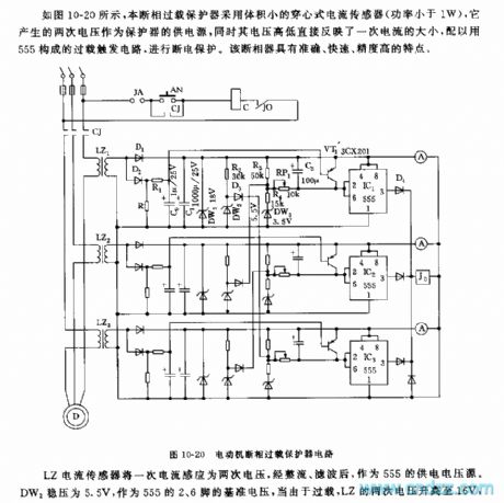
555 motor phase failure overload protector circuit
Published:2011/6/10 19:53:00 Author:nelly | Keyword: motor, phase failure overload, protector | From:SeekIC

Once current can be induced into twice voltage by LZ current sensor, after rectificated and filtered, it is used as 555's voltage supply source. The DW2 steady voltage is 5.5V, it is used as the reference voltage of 555's 2 foot and 6 foot, Due to overload, LZ's twice voltage increases to 16V, when 555's 2 foot voltage is lower than 1/3 VDD, 555 is set, J0 pulls in, the contactor CJ is power failure, motor stops running, it is protected. The adjustable delay action circuit is made of RP1 and C2, on the condition of large current or long starting time when the motor works, it will avoid power failure due to the protection.
When the motor operates normal, VT1 cuts off. When the motor stops running, D2 is low level, VT1 turns on, C2 is discharged, it can prevent error actions when the motor works again.
Reprinted Url Of This Article:
http://www.seekic.com/circuit_diagram/555_Circuit/555_motor_phase_failure_overload_protector_circuit.html
Print this Page | Comments | Reading(3)

Article Categories
power supply circuit
Amplifier Circuit
Basic Circuit
LED and Light Circuit
Sensor Circuit
Signal Processing
Electrical Equipment Circuit
Control Circuit
Remote Control Circuit
A/D-D/A Converter Circuit
Audio Circuit
Measuring and Test Circuit
Communication Circuit
Computer-Related Circuit
555 Circuit
Automotive Circuit
Repairing Circuit
Code: