555 Circuit
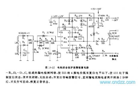
555 motor integrated protection warning device circuit
Published:2011/6/10 19:13:00 Author:nelly | Keyword: motor, integrated protection, warning device | From:SeekIC

As shown in the figure 10-12, this device is made as the core of 555. It fully uses the characteristic of time base circuit's trigger set, reset and control, such as the characteristic of 555's 4 foot's reset preferentially, it is used as the input terminal of check of leak current; when it comes overload, phase failure, short trouble, it adopts 6 foot's high impedance threshold characteristic as the overcurrent protection reset terminal; it uses 5 foot's control characteristic as overcurrent protection regulation; it uses 2 foot's high impedance terigger characteristic and 7 foot's discharge characteristic as the terigger control which is needed by delay automatical recovery; it adopts 555's high driving force(can reach 200mA) to drive SCR directly. Using a 555 circuit can achieve integrated protection control.
Reprinted Url Of This Article:
http://www.seekic.com/circuit_diagram/555_Circuit/555_motor_integrated_protection_warning_device_circuit.html
Print this Page | Comments | Reading(3)

Article Categories
power supply circuit
Amplifier Circuit
Basic Circuit
LED and Light Circuit
Sensor Circuit
Signal Processing
Electrical Equipment Circuit
Control Circuit
Remote Control Circuit
A/D-D/A Converter Circuit
Audio Circuit
Measuring and Test Circuit
Communication Circuit
Computer-Related Circuit
555 Circuit
Automotive Circuit
Repairing Circuit
Code: