555 Circuit
555 electronic storage device
Published:2011/5/2 22:54:00 Author:May | Keyword: 555, electronic, storage device | From:SeekIC

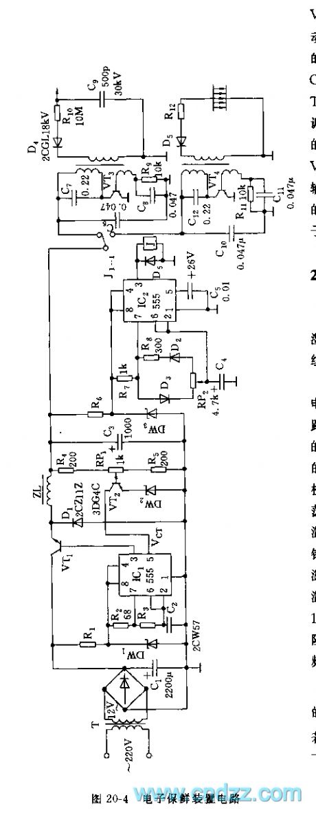
As shown in diagram 20-4, electronic storage device consists of constant voltage source, oscillator, negative-ion generator and ozone generator.
Constant voltage source adopts 555 and R2, R3, C2, etc to make up astable multivibrator, VT1 is switching regulating pipe, R4, RP1, R5 and VT2, etc make up sampling amplifier, it controls pin 5 of IC1, it can automaticly adjust 555's output pulse duty factor, thereby it can achieve the purpose of voltage regulation. D1 is fly-wheel diode. IC2 and R7, R8, RP2, C4, etc make up duty factor adjustable multivibrator type oscillator, oscillation period T=0.693(R7+R8+RP2)C4. The feature of this circuit is: when RP2 is adjusted, it not changes its oscillation frequency and only changes the duty factor of waveform. When pin 3’s output is high level, J pulls in, it makes negative-ion generator composed of VT4, etc to energized and worked. When output of 555 is low level, J is released, J1-1 is connected power supply of ozone generator, it can make the two work in turns, the released ozone and negative-ion can keep vegetables and fruits fresh.
Reprinted Url Of This Article:
http://www.seekic.com/circuit_diagram/555_Circuit/555_electronic_storage_device.html
Print this Page | Comments | Reading(3)

Article Categories
power supply circuit
Amplifier Circuit
Basic Circuit
LED and Light Circuit
Sensor Circuit
Signal Processing
Electrical Equipment Circuit
Control Circuit
Remote Control Circuit
A/D-D/A Converter Circuit
Audio Circuit
Measuring and Test Circuit
Communication Circuit
Computer-Related Circuit
555 Circuit
Automotive Circuit
Repairing Circuit
Code: