555 Circuit
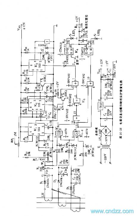
555 electrical equipment overload and open-phase protection device circuit
Published:2011/6/10 19:35:00 Author:nelly | Keyword: electrical equipment, open-phase protection device | From:SeekIC

The current transformer LH couples out the current which flows the three phase proportionally, after rectificated and filtered by D1, D2, D3, C1, C2, C3, it is added to voltage comparator and phase failure protection circuit. The voltage comparator is composed of IC1 and DW1, DW5, R7, when it passes beyond the preseting voltage, DW1 is stove in, IC1's 2 foot is high level(>1/3 VDD), IC1 is reset, it outputs low level. IC2 is set by the low jumping signal, VT1 turns on, IC3 is sealed, its output is low level. At the same time, C6 is charged by R10, RP2, when C6's voltage is charged to 2/3 VDD threshold value level, IC2 is reset, 3 foot turns to low level, VT1 is cut off, IC3's 4 foot is high level, the blockage timing is ended.
Reprinted Url Of This Article:
http://www.seekic.com/circuit_diagram/555_Circuit/555_electrical_equipment_overload_and_open_phase_protection_device_circuit.html
Print this Page | Comments | Reading(3)

Article Categories
power supply circuit
Amplifier Circuit
Basic Circuit
LED and Light Circuit
Sensor Circuit
Signal Processing
Electrical Equipment Circuit
Control Circuit
Remote Control Circuit
A/D-D/A Converter Circuit
Audio Circuit
Measuring and Test Circuit
Communication Circuit
Computer-Related Circuit
555 Circuit
Automotive Circuit
Repairing Circuit
Code: