555 Circuit
555 darkroom timer circuit 3
Published:2011/4/25 22:55:00 Author:Ecco | Keyword: 555, darkroom , timer circuit | From:SeekIC

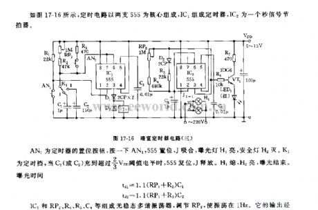
As the figure 17-16 shown, the timing circuit is composed of two branches of 555, IC1 forms a timer, IC2 is a second signal metronome. AN1 is the timer button, clicking the AN1, 555 sets, J pulls in, light exposure lamp H1 is lit, safelight H2 is off. K1 is regular file, when the C1 (or C2) is charged to more than 2/3 threshold level, the 555 resets, J releases. H1 is off, H2 is lit, exposure ended. IC2 and RP2, R4, R5, C4 etc. form astable multivibrator, adjusting the RP2 make the oscillation be 1Hz. The output of drives red LED light by VT1.
Reprinted Url Of This Article:
http://www.seekic.com/circuit_diagram/555_Circuit/555_darkroom_timer_circuit_3.html
Print this Page | Comments | Reading(3)

Article Categories
power supply circuit
Amplifier Circuit
Basic Circuit
LED and Light Circuit
Sensor Circuit
Signal Processing
Electrical Equipment Circuit
Control Circuit
Remote Control Circuit
A/D-D/A Converter Circuit
Audio Circuit
Measuring and Test Circuit
Communication Circuit
Computer-Related Circuit
555 Circuit
Automotive Circuit
Repairing Circuit
Code: