555 Circuit
555 city communication electric acousto-optical alarming circuit
Published:2011/6/8 23:40:00 Author:nelly | Keyword: city communication, electric acousto-optical, alarming | From:SeekIC

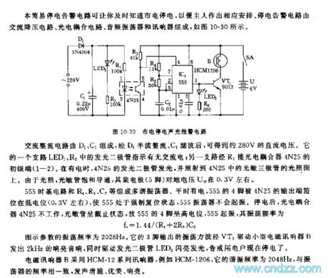
The multivibrator is composed of 555 time base circuit and R4, R5, C2. It always has electricity, 555's 4 foot is clampped to low level(about 0.3V) by 4N25's output terminal, 555 is forced in reset state, 555 oscillator does not vibrate. After power failure, the photoelectric coupler 4N25 does not work, the photosensitive tube is in off condition, so 555's 4 foot is high level, 555 starts to vibrate, the oscillation frequency fc=1.44(R4+2R5)C2.
The figured parameter's oscillation frequency is 2028Hz. Its oscillation square wave which is outputed by 3 foot sends out 2kHz sonorous sound by VT1 driving small B, at the same, it drives LED2 to flash, it warns the user that it is power failure.
Reprinted Url Of This Article:
http://www.seekic.com/circuit_diagram/555_Circuit/555_city_communication_electric_acousto_optical_alarming_circuit.html
Print this Page | Comments | Reading(3)

Article Categories
power supply circuit
Amplifier Circuit
Basic Circuit
LED and Light Circuit
Sensor Circuit
Signal Processing
Electrical Equipment Circuit
Control Circuit
Remote Control Circuit
A/D-D/A Converter Circuit
Audio Circuit
Measuring and Test Circuit
Communication Circuit
Computer-Related Circuit
555 Circuit
Automotive Circuit
Repairing Circuit
Code: