555 Circuit
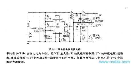
555 bipolar power conversion circuit
Published:2011/7/21 3:09:00 Author:Ecco | Keyword: 555, bipolar, power conversion | From:SeekIC

As shown in Figure 9-3, the conversion circuit includes the pulse oscillator and bipolar rectifier circuit. It is used to transfer a group of power supply into two groups of ± 12V DC voltage source in digital circuits and analog mixed circuit board with op amp. The circuit can no longer be set two voltage sources. 555 and R1, R2, C3 form a multivibrator which is in non-steady state, the oscillation frequency f = 1.44 / (R1 +2 R2) C3, the frequency of the icon parameter is about 100kHz, duty cycle is about 70%; the other way gets + 12V voltage. Load current can be up to tens of mA for 2 to 3 op amps.
Reprinted Url Of This Article:
http://www.seekic.com/circuit_diagram/555_Circuit/555_bipolar_power_conversion_circuit.html
Print this Page | Comments | Reading(3)

Article Categories
power supply circuit
Amplifier Circuit
Basic Circuit
LED and Light Circuit
Sensor Circuit
Signal Processing
Electrical Equipment Circuit
Control Circuit
Remote Control Circuit
A/D-D/A Converter Circuit
Audio Circuit
Measuring and Test Circuit
Communication Circuit
Computer-Related Circuit
555 Circuit
Automotive Circuit
Repairing Circuit
Code: