555 Circuit
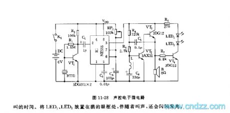
555 acoustic control electronic cat
Published:2011/7/18 5:23:00 Author:nelly | Keyword: acoustic control, electronic cat | From:SeekIC

The monostable trigger delay circuit is composed of 555 and RP1, C3. The sudden burst sound(such as clap)is changed into electrical signal by piezoceramics HTD, then it is amplified and added to 555's trigger terminal's 2 foot by VT1. Due to VT1 is saturation conduction, 2 foot's level is lower than 1/3 VDD trigger level, 555 is set, it outputs(3 foot)high level, the audio frequency oscillator obtains electricity and starts to oscillate which is composed of VT2, VT3, L, C4, C5. The oscillation time is decided by 555 monostable delay time td. td depends on the time constant of RP1, C3. After 555 circuit is set, C3 is charged by RP1, when C3's voltage is higher than 2/3 VDD, 555 is reset again, 3 foot turns into low level, the oscillator is no electricity, and it stops oscillating, the cat's noise is stopped.
Reprinted Url Of This Article:
http://www.seekic.com/circuit_diagram/555_Circuit/555_acoustic_control_electronic_cat.html
Print this Page | Comments | Reading(3)

Article Categories
power supply circuit
Amplifier Circuit
Basic Circuit
LED and Light Circuit
Sensor Circuit
Signal Processing
Electrical Equipment Circuit
Control Circuit
Remote Control Circuit
A/D-D/A Converter Circuit
Audio Circuit
Measuring and Test Circuit
Communication Circuit
Computer-Related Circuit
555 Circuit
Automotive Circuit
Repairing Circuit
Code: