555 Circuit
555 Voltage-controlled Oscillator Circuit with its Duty Cycle Controlled by Vc Terminal
Published:2011/8/1 23:41:00 Author:Zoey | Keyword: 555 Voltage-controlled Oscillator Circuit, duty cycle , Vc terminal | From:SeekIC
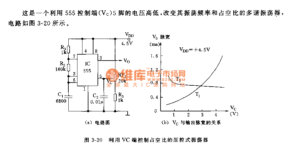
Circuit of the multi-vibratorhas beenshown in thepicture 3-20, oscillator frequency and duty cycle of the vibratorare adjusted according to the level on pin 5, which is controlled by 555 controlling terminal Vc.
A 555, R1, R2 and C1 together constitute an astable multi-vibrator. The controlling terminal can change the level it controlledthrough RP1,it also controls the voltage of comparator A1’s reverse terminal in the chip, adjusts comparator’s baseline voltage so as to change the turnover level of RS trigger and time constant of charge and discharge loop.
As illustrated in picture(b), we can take advantage of the oscillation pulse , which is voltage-controlled, to adjust the voltage of duty cycle without changing oscillation frequency, or to transfer the pulse width, pulse position as well as the voltage. Concrete operation can be seen in 5-26, 5-27 and 5-31,etc in chapter 5.
Reprinted Url Of This Article:
http://www.seekic.com/circuit_diagram/555_Circuit/555_Voltage_controlled_Oscillator_Circuit_with_its_Duty_Cycle_Controlled_by_Vc_Terminal.html
Print this Page | Comments | Reading(3)

Article Categories
power supply circuit
Amplifier Circuit
Basic Circuit
LED and Light Circuit
Sensor Circuit
Signal Processing
Electrical Equipment Circuit
Control Circuit
Remote Control Circuit
A/D-D/A Converter Circuit
Audio Circuit
Measuring and Test Circuit
Communication Circuit
Computer-Related Circuit
555 Circuit
Automotive Circuit
Repairing Circuit
Code: