555 Circuit
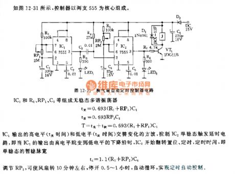
555 Ventilator automatic timing controller circuit
Published:2011/8/4 21:58:00 Author:Ecco | Keyword: 555 , Ventilator, automatic timing , controller | From:SeekIC

The controller shown as figure 12-31 is based on two roads of 555. IC1 and R1, PR1, C1 etc. form astable multivibrator. IC1 outputs alternating high and low output square wave to control the trigger IC2 monostable delay circuit, that is, when falling delay of IC1's output changes from high to low level, IC2 starts flipping set, timing.Adjusting RP2 can turn onthe fan for about 10 minutes and close 0.5 to 1 hour, it will change in automatic cycle to achieve automatic control of time.
Reprinted Url Of This Article:
http://www.seekic.com/circuit_diagram/555_Circuit/555_Ventilator_automatic_timing_controller_circuit.html
Print this Page | Comments | Reading(3)

Article Categories
power supply circuit
Amplifier Circuit
Basic Circuit
LED and Light Circuit
Sensor Circuit
Signal Processing
Electrical Equipment Circuit
Control Circuit
Remote Control Circuit
A/D-D/A Converter Circuit
Audio Circuit
Measuring and Test Circuit
Communication Circuit
Computer-Related Circuit
555 Circuit
Automotive Circuit
Repairing Circuit
Code: