555 Circuit
555 Time-Base Circuit Internal Structure Circuit
Published:2011/7/8 21:25:00 Author:Robert | Keyword: Time-Base, Internal, Structure | From:SeekIC


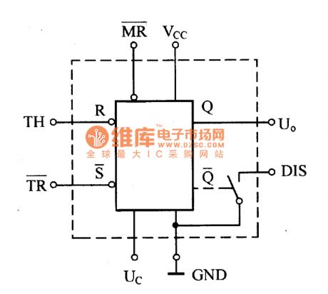
The 555 time-base circuit is divided into two categories which are TTL type and CMOS type. The picture shows the TTL type circuit's internal structure circuit. From the picture we notice that it is made up of voltage divider, comparator, R-S trigger, output stage and discharging switch and so on. The comparator's main function in the circuit is to compare the input voltage to the reference voltage formed by the voltage divider. And it would show the comparing result by outputing high voltage level 1 or low voltage level 0 in its output port. The 555 circuit's R-S trigger is made up of two NAND gates with cross connection. In order to reset the R-S trigger to zero directly, the trigger is lead to a MR port. It could simply set the MR port to low voltage level 0 , the trigger would be set to zero immediately which means Q=0=Uo, no matter what original status the trigger has and no matter what signal the trigger's input port is added. So the MR port is also known as the total-reset port.
Reprinted Url Of This Article:
http://www.seekic.com/circuit_diagram/555_Circuit/555_Time_Base_Circuit_Internal_Structure_Circuit.html
Print this Page | Comments | Reading(3)

Article Categories
power supply circuit
Amplifier Circuit
Basic Circuit
LED and Light Circuit
Sensor Circuit
Signal Processing
Electrical Equipment Circuit
Control Circuit
Remote Control Circuit
A/D-D/A Converter Circuit
Audio Circuit
Measuring and Test Circuit
Communication Circuit
Computer-Related Circuit
555 Circuit
Automotive Circuit
Repairing Circuit
Code: