555 Circuit
555_TIMER_AS_FLIP_FLOP
Published:2009/7/1 20:21:00 Author:May | From:SeekIC

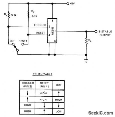
Eliminating RC timing network of 555 timer and tying threshold low makes output states depend on trigger and reset inputs. These are pulled high through R1 and R2, then pulled low either with switch or TTL level of 0 on reset input pin 4. Output then stays low until reset goes high and trigger goes low; this bistable action prevents contact bounce from switching output erroneously. Circuit will source or sink 200 mA.-R. L. Gephart, Mini-DIP Bistable Flip-Flop Sinks or Sources 200 mA, EDN Magazine, Oct. 5, 1974, p 76 and 78.
Reprinted Url Of This Article:
http://www.seekic.com/circuit_diagram/555_Circuit/555_TIMER_AS_FLIP_FLOP.html
Print this Page | Comments | Reading(3)

Article Categories
power supply circuit
Amplifier Circuit
Basic Circuit
LED and Light Circuit
Sensor Circuit
Signal Processing
Electrical Equipment Circuit
Control Circuit
Remote Control Circuit
A/D-D/A Converter Circuit
Audio Circuit
Measuring and Test Circuit
Communication Circuit
Computer-Related Circuit
555 Circuit
Automotive Circuit
Repairing Circuit
Code: