555 Circuit
555 Symmetrical wave Multi-vibrator
Published:2011/7/4 22:58:00 Author:Zoey | Keyword: 555 Multi-vibrator, Symmetrical wave | From:SeekIC


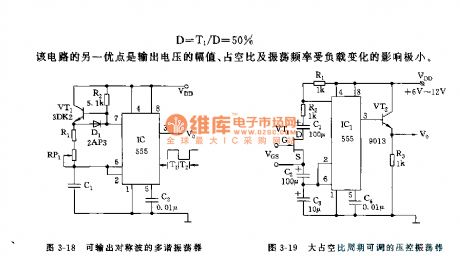
As shown in the figure 3-18, this multi-vibrator has added a positive bias triode VT1. With the positive bias effect of R2, VT1 can be fully conducted; but as soon as C1 discharges, it will not be conducted. As the switch pipe VT1 and Germanium diode is in the state of conduction, the positive conduction resistance is weak, so it has little effect on charge and discharge time constant. The charge time, discharge time, oscillation period and duty cycle can be calculated by following formula:
T1=0.693(R1+RP1)•C1
T2=0.693(R1+RP1)•C1
T=0.693(2R1+2RP1)•C1
D=T2/D=50%
Another merit of this circuit is, the load change has little effect on voltage output, duty cycle and oscillation frequency.
Figure 3-18 Multi-vibrator that can output symmetrical wave
Figure 3-19 Voltage-controlled oscillator with an adjustable duty cycle period
Reprinted Url Of This Article:
http://www.seekic.com/circuit_diagram/555_Circuit/555_Symmetrical_wave_Multi_vibrator.html
Print this Page | Comments | Reading(3)

Article Categories
power supply circuit
Amplifier Circuit
Basic Circuit
LED and Light Circuit
Sensor Circuit
Signal Processing
Electrical Equipment Circuit
Control Circuit
Remote Control Circuit
A/D-D/A Converter Circuit
Audio Circuit
Measuring and Test Circuit
Communication Circuit
Computer-Related Circuit
555 Circuit
Automotive Circuit
Repairing Circuit
Code: