555 Circuit
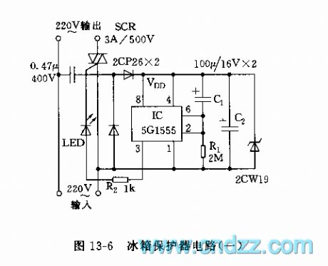
555 Refrigerator protector circuit 1
Published:2011/10/18 3:45:00 Author:Ecco | Keyword: 555 , Refrigerator protector | From:SeekIC

The circuit is shown in Figure 13-6, the circuit is based on 555 circuit to form power delay protection circuit. The connection of C1 makes pin 6 be in high level, and pin 3 be in low level, when the supply is turned again after failure, SCR is cut off. C1 charges, so the pin 2 is lower than the trigger time of 1/3 vdd, that is the delay time td. Icon corresponding td parameter is about 6 minutes. Setting to 555, pin 3 outputs high level. SCR turns on, the refrigerator gets power and the working indicator LED is lit.
Reprinted Url Of This Article:
http://www.seekic.com/circuit_diagram/555_Circuit/555_Refrigerator_protector_circuit_1.html
Print this Page | Comments | Reading(3)

Article Categories
power supply circuit
Amplifier Circuit
Basic Circuit
LED and Light Circuit
Sensor Circuit
Signal Processing
Electrical Equipment Circuit
Control Circuit
Remote Control Circuit
A/D-D/A Converter Circuit
Audio Circuit
Measuring and Test Circuit
Communication Circuit
Computer-Related Circuit
555 Circuit
Automotive Circuit
Repairing Circuit
Code: