555 Circuit
555 Linear voltage / frequency converter circuit 3
Published:2011/9/18 21:48:00 Author:Ecco | Keyword: 555, Linear voltage , frequency , converter | From:SeekIC
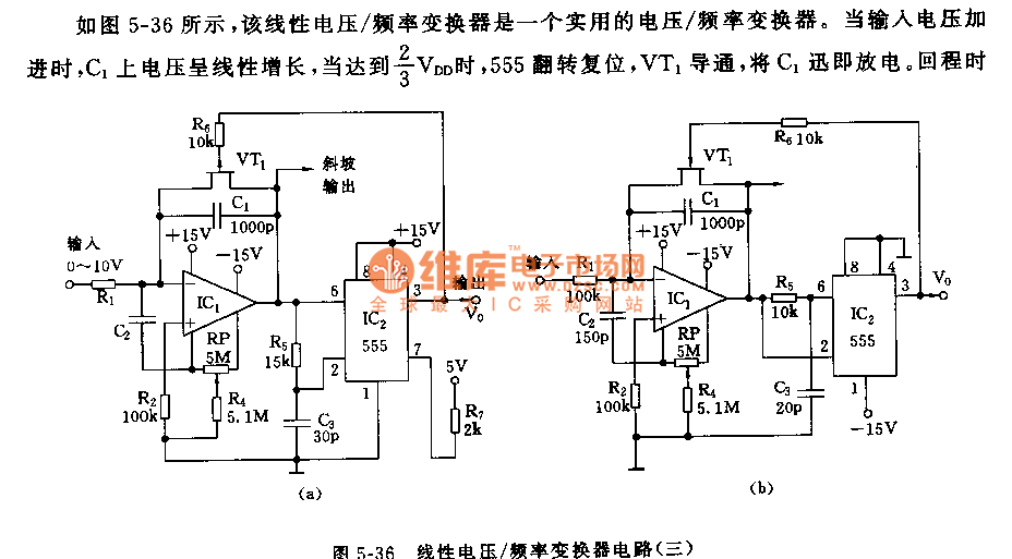
As shown in Figure 5-36, the linear voltage/frequency converter is a practical voltage/frequency converter. When added to the input voltage, the voltage on C1 increases linearly, when it is reached 2/3 VDD, the 555 flip sets, VT1 is conducted, C1 quickly discharges. Round trip time is also associated with the R5,C3 time constant, that is, when the voltage of C3 decreases to 1/3 VDD, the 555 sets. VT1 is cut off, then it starts the next time. The circuit's return time is about 1μs. When the frequency is over 10KHz, the nonlinear error is about 0.2%.
Reprinted Url Of This Article:
http://www.seekic.com/circuit_diagram/555_Circuit/555_Linear_voltage___frequency_converter_circuit_3.html
Print this Page | Comments | Reading(3)

Article Categories
power supply circuit
Amplifier Circuit
Basic Circuit
LED and Light Circuit
Sensor Circuit
Signal Processing
Electrical Equipment Circuit
Control Circuit
Remote Control Circuit
A/D-D/A Converter Circuit
Audio Circuit
Measuring and Test Circuit
Communication Circuit
Computer-Related Circuit
555 Circuit
Automotive Circuit
Repairing Circuit
Code: