555 Circuit
555 Linear Voltage/Frequency Converter circuit (Two)
Published:2011/7/4 23:03:00 Author:Zoey | Keyword: Linear Voltage, Frequency Converter, circuit | From:SeekIC
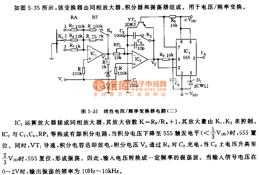
As shown in the picture 5-35, this converter is composed of a non-inverting amplifier, an integrator and an oscillator for voltage/frequency conversion.
When jointed to the amplifier, amplification factor K=RF/RA+1 and it is controlled by K1 and K2. IC2, C1, C4 and RP1 constitute a circuit with an active integral, when integral voltage declines to 555 trigger level(<1/3VDD), 555 will set. Meanwhile, VT1 will conduct; integral capacitance will discharge promptly, integral voltage V2 will charge to C2 via R9. When voltage on C2 ascends to 2/3VDD, 555 will reset and give rise to oscillation. Therefore, voltage input is converted to oscillation wave with some frequencies. When input signal ranges from 0 to 2V, frequency of input oscillation varies within the limit from 10Hz to 10 kHz.
Reprinted Url Of This Article:
http://www.seekic.com/circuit_diagram/555_Circuit/555_Linear_Voltage_Frequency_Converter_circuit_Two.html
Print this Page | Comments | Reading(3)

Article Categories
power supply circuit
Amplifier Circuit
Basic Circuit
LED and Light Circuit
Sensor Circuit
Signal Processing
Electrical Equipment Circuit
Control Circuit
Remote Control Circuit
A/D-D/A Converter Circuit
Audio Circuit
Measuring and Test Circuit
Communication Circuit
Computer-Related Circuit
555 Circuit
Automotive Circuit
Repairing Circuit
Code: