555 Circuit
555 Linear Voltage/Frequency Converter Circuit (Three)
Published:2011/7/5 0:07:00 Author:Zoey | Keyword: 555 Linear Voltage, Frequency Converter, Circuit | From:SeekIC
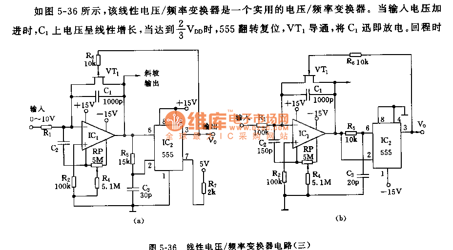
As shown in the picture 5-36, this linear voltage/frequency converter is a practical voltage/frequency converter. When input voltage is strengthened, voltage on C1 will have a linear increase, when it reaches 2/3 VDD, VT1 will conduct and make VT1 discharge promptly. Backhaul time is related to R5C3 time constant. That is,as soon asvoltage on C3 declines to 1/3 VDD, 555 will reset.VT1 will ceases to work, then next timing begins.
Backhaul time of this circuit is only 1μs. The relationship between voltage input and converter frequency can be expressed by following formula:
f=3/2•Vin/VDDR1C1
V/F of parameter in the picture is f ≈10³Vin. If frequency exceeds 10kHz, nonlinear error will be about 0.2%.
Reprinted Url Of This Article:
http://www.seekic.com/circuit_diagram/555_Circuit/555_Linear_Voltage_Frequency_Converter_Circuit_Three.html
Print this Page | Comments | Reading(3)

Article Categories
power supply circuit
Amplifier Circuit
Basic Circuit
LED and Light Circuit
Sensor Circuit
Signal Processing
Electrical Equipment Circuit
Control Circuit
Remote Control Circuit
A/D-D/A Converter Circuit
Audio Circuit
Measuring and Test Circuit
Communication Circuit
Computer-Related Circuit
555 Circuit
Automotive Circuit
Repairing Circuit
Code: