555 Circuit
555_LATCH
Published:2009/7/14 12:10:00 Author:May | From:SeekIC

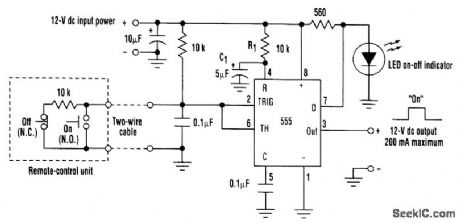
Using a 555 chip in the memory mode, this push-button-cont rolled latch switch can source up to 200 mA of load current. Only one pair of wires is required to interface the ON and OFF push buttons to the control circuitry. The memory-mode feature of the 555 chip is implemented by connecting the trigger (pin 2) and threshold (pin 6) inputs together and applying one-half the supply voltage via a resistor network. Momentarily forcing the input low causes the output to go high, while forcing the input high causes the output to go low. To facilitate remote operation of the latch switch using one pair of wires, one resistor in the voltage-divider network is installed in the remote-control unit. Shorting this resistor out with the ON push button causes the output to go high. Conversely, opening this resistor with the OFF push button induces the output to go low. The R1-C1 network connected to the RESET input (pin 4) forces the latch to come up in the OFF state when power is first applied. The LED on-off indicator is kept off whenever the discharge output (pin 7) is conducting. When the output (pin 3) goes high.
Reprinted Url Of This Article:
http://www.seekic.com/circuit_diagram/555_Circuit/555_LATCH.html
Print this Page | Comments | Reading(3)

Article Categories
power supply circuit
Amplifier Circuit
Basic Circuit
LED and Light Circuit
Sensor Circuit
Signal Processing
Electrical Equipment Circuit
Control Circuit
Remote Control Circuit
A/D-D/A Converter Circuit
Audio Circuit
Measuring and Test Circuit
Communication Circuit
Computer-Related Circuit
555 Circuit
Automotive Circuit
Repairing Circuit
Code: