555 Circuit
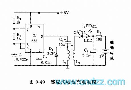
555 Inductive battery charging circuit
Published:2011/9/18 21:15:00 Author:Ecco | Keyword: 555, Inductive , battery, charging circuit | From:SeekIC

As shown in Figure 9-40, 555 and R1, R2, C1 form an astable multivibrator, f = 1.44/ (R1 +2 R2) C1, the oscillation frequency of the icon parameter is approximately 10kHz. The oscillation square wave is added to the primary L1, secondary L2 of inductively coupled coil, and two nickel-cadmium batteries are mounted in the dielectric plexiglass shell, that is, it uses inductive charging method. The core of coil antenna uses φ10 magnet bar of radio, it uses φ0.13mm and φ0.27mm wires with 200turns on the primary and secondary coils, the middle is cut and connected in the both sides of dielectric plexiglass panels. Battery charging current is up to 10mA, when it is charging, LED is lit.
Reprinted Url Of This Article:
http://www.seekic.com/circuit_diagram/555_Circuit/555_Inductive_battery_charging_circuit.html
Print this Page | Comments | Reading(3)

Article Categories
power supply circuit
Amplifier Circuit
Basic Circuit
LED and Light Circuit
Sensor Circuit
Signal Processing
Electrical Equipment Circuit
Control Circuit
Remote Control Circuit
A/D-D/A Converter Circuit
Audio Circuit
Measuring and Test Circuit
Communication Circuit
Computer-Related Circuit
555 Circuit
Automotive Circuit
Repairing Circuit
Code: