555 Circuit
555 Closed Loop Three-phase Multi-vibrator Circuit
Published:2011/6/28 3:19:00 Author:Zoey | Keyword: 555 Closed Loop, Three-phase Multi-vibrator, Circuit | From:SeekIC


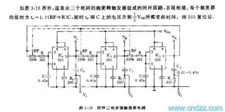
As shown in the picture 3-16, this closed loop is composed of three identical Smit triggers, end to end, the detained time of every trigger td=1.1(RP+R)C, the detained time td refers to the time needed for voltage on C ascend to 1/3 VDD. After 555 has reposited, load on C discharges to output terminal pin 3 of IC through R, W. therefore it has a same charge time constant. If the output terminals of any trigger changes, the circuit has to transmit circuit through three monostable triggers, the needed time is 3td. Output period of every IC T is 6td, the relevant frequency is
f=1/T=1/6X (RP+R) C
Value of the differential circuit R1 and C1 is selected according to the pulse width and load needed.
Three-phase signal source is widely applied in equipment like three-phase power supply, three-phase asynchronous electromotor, three-phase countercurrent, and demo teaching as well as circular lampions.
Reprinted Url Of This Article:
http://www.seekic.com/circuit_diagram/555_Circuit/555_Closed_Loop_Three_phase_Multi_vibrator_Circuit.html
Print this Page | Comments | Reading(3)

Article Categories
power supply circuit
Amplifier Circuit
Basic Circuit
LED and Light Circuit
Sensor Circuit
Signal Processing
Electrical Equipment Circuit
Control Circuit
Remote Control Circuit
A/D-D/A Converter Circuit
Audio Circuit
Measuring and Test Circuit
Communication Circuit
Computer-Related Circuit
555 Circuit
Automotive Circuit
Repairing Circuit
Code: