555 Circuit
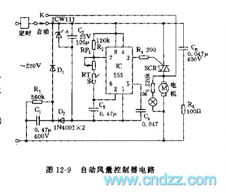
555 Automatic fan speed controller circuit
Published:2011/8/4 22:00:00 Author:Ecco | Keyword: 555 , Automatic, fan speed , controller | From:SeekIC

As shown in Figure 12-9, the controller circuit consists of step-down rectifier circuit and an oscillator and control circuit. 555 and R2, RP1, C3 and thermistor RT form a non-steady multivibrator, the oscillation frequency f = 1.44 / (R2 + RP1 +2 RT) C3. It can be shown by the formula, the oscillation frequency is related to RT. When it selects a negative temperature coefficient thermistor, the temperature rises, RT resistance decreases, the oscillation frequency increases, and the duty cycle increases, the motor conduction timeincreases, natural wind increases; or the temperature drops, the power-on time reduces, the natural wind is weaken.
Reprinted Url Of This Article:
http://www.seekic.com/circuit_diagram/555_Circuit/555_Automatic_fan_speed_controller_circuit.html
Print this Page | Comments | Reading(3)

Article Categories
power supply circuit
Amplifier Circuit
Basic Circuit
LED and Light Circuit
Sensor Circuit
Signal Processing
Electrical Equipment Circuit
Control Circuit
Remote Control Circuit
A/D-D/A Converter Circuit
Audio Circuit
Measuring and Test Circuit
Communication Circuit
Computer-Related Circuit
555 Circuit
Automotive Circuit
Repairing Circuit
Code: