
Project Solutions
HIGH-END POWER AMP-High-class watts (7)
Published:2011/8/22 21:46:00 Author:Phyllis From:SeekIC
By Ton Giesbets
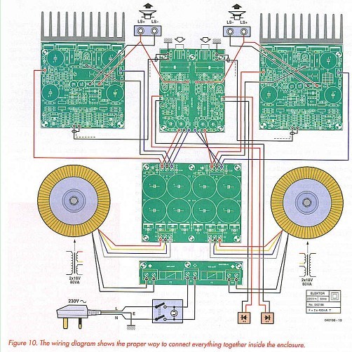
For each power supply terminal, insert the supply leads for the amplifier boards and indicator board together in the appropriate terminal blocks. Heavy wire with a cross-sectional area of 2.5 mm2 must be used for the amplifier boards, but thin flexible wire is adequate for the overdrive indicator board. Make the supply leads for the amplifier boards as short and direct as possible. We crimped tab connectors to the ends of the leads, but you can also solder them directly to the boards. Connect the speaker outputs on the circuit boards to the output sockets in the same manner. At the sockets, we simply fitted wire lugs to the ends of the wires, which avoid the contact resistance of an additional plug. The power supply leads for the overdrive indicator board can be simply soldered in place. Fit the overdrive indicator board in the middle between the amplifier boards. The input sockets will then be almost flush with the rear panel. Naturally, it will take a bit of measuring and fitting to get the holes for the connectors in the right places.
The manner in which the heat sinks are attached causes the mounting surface to be approximately 6 mm away from the edge of the circuit board, assuming that the amplifier circuit boards are attached directly to the rails. This means that the leads of the transistors must be bent twice allow them to be positioned correctly without creating permanent mechanical stresses in the transistors. For the large output transistors, the first bend will have to be somewhat closer to the plastic package than what is intended (in the wide part), since otherwise the leads will touch the rails or won’t fit at all. Another possibility, which has the disadvantage that it weakens the structure, is to file away enough metal at the appropriate locations to provide adequate clearance. We intentionally rejected this option.
Once you have taken care of this detail and the transistors can easily be placed flat against the heat sink with their leads passing freely through the holes in the circuit board, you can mark the locations of the mounting holes on the back of the heat sink. Naturally, you should do this before the transistors have been soldered to the circuit board, but after the final holes for fastening the amplifier circuit boards have been made in the bottom plate. Once the output transistors and their drivers have been fitted to the heat sink and soldered to the circuit boards, the bottom plate can be removed quite easily.
Be sure to not exert too much force on the leads of the transistors when the boards are suspended this way.
Power transistors T14 and T15 must bs fitted to the heat sink using insulators (mica washers), while the other three transistors (Til, T12 and T13) can be screwed directly to the heat sink. Be sure to use thermal paste with all of the transistors.
After you have made all the mounting holes for the remaining circuit boards, transformers, mains switch and LEDs (in the front panel) and ventilation holes in the enclosure, you can screw everything else in place and fit the wiring.
Use well-screened audio cable to connect the inputs of the amplifier boards to the terminals near the input sockets on the overdrive indicator board. Use the two ground terminals next to the input sockets to connect the enclosure to the grounds of the two channels. This avoids creating any ground loops. The measurement inputs for the amplifier output signals are located in the middle of the overdrive indicator board. The easiest way to connect them is to use thin, flexible wire to connect them to the output sockets.
For the sake of clarity, the complete wiring diagram of the final amplifier is shown in Figure 10. 
One of the cover panels for the enclosure is solid, while the other one has punched perforations. To keep the assembly sturdy, we decided to use the solid panel for the bottom panel and the ’open’ panel for the top panel, which provides continuous ventilation for the enclosure. However, we recommend making additional ventilation holes in the bottom panel near the amplifier circuit boards to provide additional cooling for T7-T10.
Reprinted Url Of This Article: http://www.seekic.com/blog/project_solutions/2011/08/22/HIGH_END_POWER_AMP_High_class_watts_(7).html
Print this Page | Comments | Reading(1765)
Article Categories
New published articles
· Imagination works with TSMC to develop FinFET process
Author:Ecco Reading(33516)
· XMOS pushes event-driven MCUs with lower price
Author:Ecco Reading(3534)
· Intel brings upgraded 32-nm SoC for smartphones
Author:Ecco Reading(3250)
· Micron pushes TLC 128-Gbit NAND flash
Author:Ecco Reading(3816)
· Intel will stop supplying desktop motherboards
Author:Ecco Reading(5341)
· Processor market was expected to regain strength in 2013
Author:Ecco Reading(3318)
· It was reported that TSMC sales fall steeply
Author:Ecco Reading(3474)
· Cisco, NXP work with auto wireless startup
Author:Ecco Reading(3620)
· Micron was impacted by manufacturing glitch
Author:Ecco Reading(4017)
· China can make 22-nm transistor by themselves
Author:Ecco Reading(3819)
· Chip market rebound is coming, according to survey
Author:Ecco Reading(3760)
· Sony, Toshiba will spend more on chips, iSuppli reports
Author:Ecco Reading(3790)
· Qualcomm becomes the 13th company to join NFC Forum board
Author:Ecco Reading(6103)
· TSMC increases building work for FinFET fab
Author:Ecco Reading(3778)
· TI plans to cut 1,700 jobs in OMAP shift
Author:Ecco Reading(4587)