
Project Solutions
LED Bedside Lamp: with turn-off delay
Published:2011/8/21 21:36:00 Author:Li xiao na From:SeekIC
By Eduard Heger
If you are not lucky enough to have access to expensive test gear then lamp circuits using LEDs offer a good chance of success and allow a little bit of electronic experimentation.
simple but useful addition to the bedside table. The lamp is activated either by pressing a push button or automatically when the in-built microphone detects a noise. Once lit the LED remains on for a predetermined time. The circuit has quite modest power requirements and four recharge-use before they need to be topped up. The complete circuit takes around 400μA in standby and 24 mA with the LED burning.
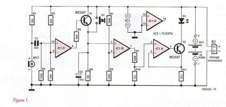
The microphone requires a connection to the positive supply via Rl and the circuit diagram (Figure 1) shows it AC coupled to IC1.C. The microphone sensitivity is to some extent governed by the value of R1. 
A value of 15 kΩ is recommended but it may need to be changed to suit the sensitivity of your particular microphone capsule. At maximum sensitivity the LED was triggered by pressure on the microphone diaphragm from a draft of air produced when the bedroom door was opened!
Capacitor C1 is used to remove the DC component of the microphone signal while R2 ensures the resultant AC signal is referenced to earth potential. Resistors R3 and R4 form a potential divider to provide the voltage threshold at the negative input of comparator 1C1.C. Whenever the signal level produced by the noise exceeds this threshold value the output will go high and switch on T l. Capacitor C2 will then be charged and the voltage level on the positive input of 1C1.B will rise exponentially. Pressing pushbutton SI will have the same effect because it is wired in parallel with T l. The charging path of C2 has no series resistor so even a very short duration sound will be sufficient for C2 to fully charge. ICl.13 is configured as a comparator with resistors R7/R8 forming a potential divider defining the threshold voltage of 20 % of the supply voltage {about 1 V) at the inverting input. When C2 is fully charged it takes around 1.5 min for the voltage to fall to this level while discharging through resistor R6.
The last opamp IC1.A is configured as an amplifier together with transistor T2. The LED current (and hence brightness) can be altered by changing the value of R11 (lLKD = 0-44 V/R11). The voltage developed across R11 is used by IC1.A to control the conduction of T2 in a classic feedback configuration. This ensures that the light intensity of Dl remains constant even when the battery output voltage sinks to the sharp ’knee’ in its characteristic. Connector K1 allows an external charger to recharge the cells. 
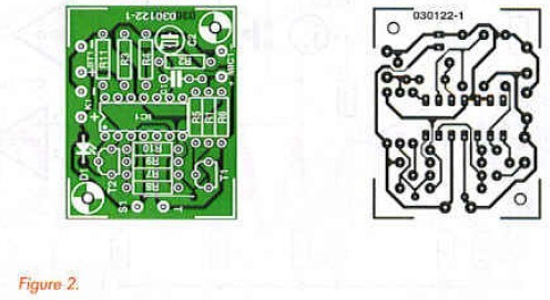
The PCB component placement (including a socket for IC1) is shown in Figure 2. It is not necessary to fit any wire links and apart from the semiconductors there is only one polarised component (C2). It may be tempting fate but there is hardly any opportunity to fit any component incorrectly! The LED is soldered in place once the PCB is fitted into its enclosure and the LED positioned through an opening. A reflector can be fitted to help concentrate the LED light.
Wire connections to the PCB can be made vie solder pins. It may be possible to connect the charging socket and pushbutton directly to the relevant pins without the need (or wire but this will depend on the type of enclosure that you use. The microphone capsule can be mounted inside the case but don’t forget to provide an opening to allow sound waves to reach the microphone.
Reprinted Url Of This Article: http://www.seekic.com/blog/project_solutions/2011/08/21/LED_Bedside_Lamp__with_turn_off_delay.html
Print this Page | Comments | Reading(1619)
Article Categories
New published articles
· Imagination works with TSMC to develop FinFET process
Author:Ecco Reading(33516)
· XMOS pushes event-driven MCUs with lower price
Author:Ecco Reading(3534)
· Intel brings upgraded 32-nm SoC for smartphones
Author:Ecco Reading(3250)
· Micron pushes TLC 128-Gbit NAND flash
Author:Ecco Reading(3816)
· Intel will stop supplying desktop motherboards
Author:Ecco Reading(5341)
· Processor market was expected to regain strength in 2013
Author:Ecco Reading(3318)
· It was reported that TSMC sales fall steeply
Author:Ecco Reading(3474)
· Cisco, NXP work with auto wireless startup
Author:Ecco Reading(3620)
· Micron was impacted by manufacturing glitch
Author:Ecco Reading(4017)
· China can make 22-nm transistor by themselves
Author:Ecco Reading(3819)
· Chip market rebound is coming, according to survey
Author:Ecco Reading(3760)
· Sony, Toshiba will spend more on chips, iSuppli reports
Author:Ecco Reading(3790)
· Qualcomm becomes the 13th company to join NFC Forum board
Author:Ecco Reading(6103)
· TSMC increases building work for FinFET fab
Author:Ecco Reading(3778)
· TI plans to cut 1,700 jobs in OMAP shift
Author:Ecco Reading(4587)