
Project Solutions
HIGH-END POWER AMP-High-class watts (1)
Published:2011/8/21 20:38:00 Author:Phyllis From:SeekIC
By Ton Giesbets
The High-End Preamp preamplifier published in the April & May 2004 issues naturally calls for a matching final amplifier in an identical housing. Due to the restricted size of the enclosure, the output power of this final amplifier is somewhat on the modest side, but the quality is outstanding - and it is more than adequate for filling an average living room with an impressive sound image.
The Audio Link amplifier, published a year ago, was well received by audio enthusiasts due to its very convenient user interface and high-quality, no-nonsense signal processing A matching final amplifier must naturally have the same level of quality, and here we have made an extra effort to achieve this result. Our desire to use an identical enclosure meant that there wasn’t all that much space available, and the maximum output power of a final amplifier largely depends on its size. The dimensions of the heat sinks and transformers are particularly restricted by the size of the enclosure. We managed to achieve a bit less than 50 watts into 4 ohms, using 80-VA toroidal transformers.
This amplifier is thus primarily suitable for people who like to listen to music at a ’civilized’ volume and are very demanding with regard to reproduction quality.
As the output power is distinctly less than what many of our previous (discrete) final amplifiers can provide, we added an accurate overdrive indicator to this design. It compares the input and output signals of the final amplifier and lights up an LED if the difference is too large. This enables the listener to keep a good eye on the output drive level.
Output stage
Readers who have paid attention the schematic diagrams of our final amplifiers during recent years will see a lot of familiar features in the present design. There aren’t any real surprises, and the sound quality is determined more by the choice of transistors and the circuit board layout than by the circuit design.
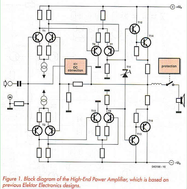
As you can see from the block diagram in Figure 1, each channel of the amplifier essentially consists of two differential amplifiers and an emitter follower, but with a fully symmetrical design. There is also an integrator that eliminates any DC offset voltage at the output. 

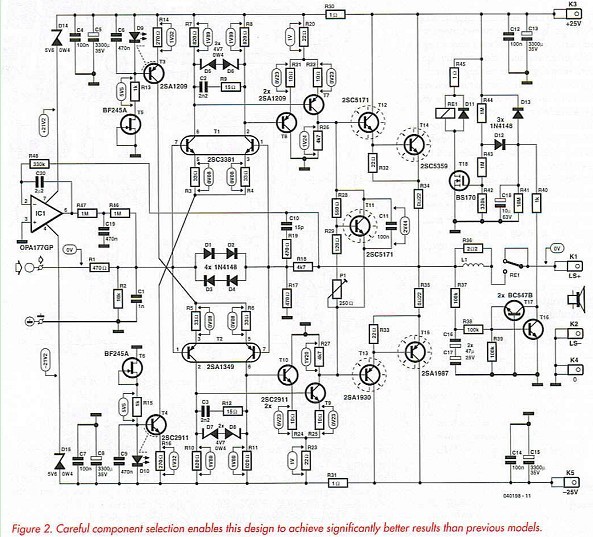
The input stage differential amplifier (Figure 2) consists of two complementary dual transistors (Tla/Tlb and T2a/T2b) from Toshiba. It is followed by a second set of differential amplifiers (T7/T8 and T9/T10), which provide most of the gain. The combination of T7 and T9 also forms a push-pull amplifier that can supply more than enough current to drive the emitter-follower output stage. The operating points of these differential amplifiers are determined entirely by the operating points of Tl and T2. The currents through the differential transistors in the second stage of the amplifier are determined by R20-R22 or R23-R25 and the voltage across R7/R8 or R10/R11, respectively. The voltages across the collector resistors of the input pairs are in turn determined by constant-current sources T3 and T4.
Reprinted Url Of This Article: http://www.seekic.com/blog/project_solutions/2011/08/21/HIGH_END_POWER_AMP_High_class_watts_(1).html
Print this Page | Comments | Reading(7187)
Article Categories
New published articles
· Imagination works with TSMC to develop FinFET process
Author:Ecco Reading(33516)
· XMOS pushes event-driven MCUs with lower price
Author:Ecco Reading(3534)
· Intel brings upgraded 32-nm SoC for smartphones
Author:Ecco Reading(3250)
· Micron pushes TLC 128-Gbit NAND flash
Author:Ecco Reading(3816)
· Intel will stop supplying desktop motherboards
Author:Ecco Reading(5341)
· Processor market was expected to regain strength in 2013
Author:Ecco Reading(3318)
· It was reported that TSMC sales fall steeply
Author:Ecco Reading(3474)
· Cisco, NXP work with auto wireless startup
Author:Ecco Reading(3620)
· Micron was impacted by manufacturing glitch
Author:Ecco Reading(4017)
· China can make 22-nm transistor by themselves
Author:Ecco Reading(3819)
· Chip market rebound is coming, according to survey
Author:Ecco Reading(3760)
· Sony, Toshiba will spend more on chips, iSuppli reports
Author:Ecco Reading(3790)
· Qualcomm becomes the 13th company to join NFC Forum board
Author:Ecco Reading(6103)
· TSMC increases building work for FinFET fab
Author:Ecco Reading(3778)
· TI plans to cut 1,700 jobs in OMAP shift
Author:Ecco Reading(4587)