
Project Solutions
Wireless Microphone: Audio in the ISM band 4
Published:2011/8/19 2:15:00 Author:Amy From:SeekIC
Ton Giesberts
Interface
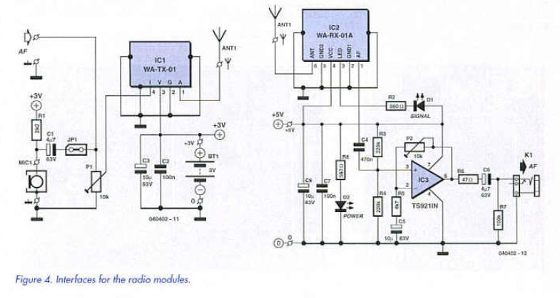
Thanks to these complex modules that include almost all the necessary electronics, what remains is straightforward. Figure 4 shows the two parts of the circuit. In the transmitter we can either connect a microphone or any other desired audio source with a maximum output level of -15 dBV. In most cases, however, an electrets microphone will be used. There is a small offset voltage present at the AF input with PI adjusted to maximum: in our prototype we measured about 0.15 V If a dynamic microphone is to be connected, it is essential to add a coupling capacitor. Alternatively, omit Rl and connect the dynamic microphone In place of the electret microphone. PI can be used to attenuate microphone signals that are too high, so that the radio module is not overdriven. 
The receiver circuit is slightly less simple. The receiver module has two outputs, one for the signal itself and one which indicates whether the signal strength is adequate or whether the muting circuit has been triggered. Since we have plenty of power to spare at the receiver (battery operation here is not essential) we can afford an extra indicator in the form of LED Dl.
In order to amplify the output of the receiver module (which, at 10 kΩ, is not exactly low impedance), we have added a buffer amplifier. This is a classical non-inverting AC amplifier built around a rail-to-rail opamp which can operate from a voltage of between 2.7 V and 12 V, almost the same range as for the module. We have shown a supply voltage of 5 V. although 3 V or 12 V would do just as well. If a different (non-rail-to-rail) opamp were used, a supply voltage of 5 V would be required- Many opamps will only operate correctly with a sympatric power supply of ±5 V or with an asymmetric 10 V supply. A further advantage of the TS921 used he>e is its high output drive capability: it can directly drive headphones or even two 3211 headphone transducers wired in parallel although in this case C6 should be replaced by a 100 pF 10 V type. The 47 n output resistor protects the opamp from the inductive load of a shielded cable and from short circuits. Trimmer potentiometer P2 allows the gain to lie adjusted from unity (P2 at minimum resistance) to 10 dB (P2 at maximum resistance. C6 removes any DC component from the output and R7 ensures that there is always a load at the output. Since the opamp has asymmetrical supplies, a capacitor (C5) is also required in the feedback circuit. R3 and R4 set the operating point of die opamp at half the supply voltage. C7 and CB provide extra power supply decoupling. At higher supply voltages it is necessary to increase the current-limiting resistors for the low-current LEDs so that the current through them does not exceed about 2 mV
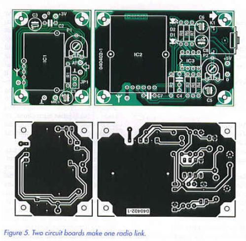
We have designed a two-part printed circuit board to accommodate the radio modules and the few external components (Figure 5). The layout is designed for optimum audio performance, The components should be fitted to the board, observing that the transmitter module can only be fitted to the copper side. An ordinary 3.5 mm jack socket provides the audio output. 
All that remains are the antennas. In principle a stiff piece of wire with length 1/4 X (78 mm at 860 MHz) will do the job; mote professional antennas can be found on the Circuit Design website at http://www.cdt21.com/.
Reprinted Url Of This Article: http://www.seekic.com/blog/project_solutions/2011/08/19/Wireless_Microphone__Audio_in_the_ISM_band_4.html
Print this Page | Comments | Reading(3732)
Article Categories
New published articles
· Imagination works with TSMC to develop FinFET process
Author:Ecco Reading(33516)
· XMOS pushes event-driven MCUs with lower price
Author:Ecco Reading(3534)
· Intel brings upgraded 32-nm SoC for smartphones
Author:Ecco Reading(3250)
· Micron pushes TLC 128-Gbit NAND flash
Author:Ecco Reading(3816)
· Intel will stop supplying desktop motherboards
Author:Ecco Reading(5341)
· Processor market was expected to regain strength in 2013
Author:Ecco Reading(3318)
· It was reported that TSMC sales fall steeply
Author:Ecco Reading(3474)
· Cisco, NXP work with auto wireless startup
Author:Ecco Reading(3620)
· Micron was impacted by manufacturing glitch
Author:Ecco Reading(4017)
· China can make 22-nm transistor by themselves
Author:Ecco Reading(3819)
· Chip market rebound is coming, according to survey
Author:Ecco Reading(3760)
· Sony, Toshiba will spend more on chips, iSuppli reports
Author:Ecco Reading(3790)
· Qualcomm becomes the 13th company to join NFC Forum board
Author:Ecco Reading(6103)
· TSMC increases building work for FinFET fab
Author:Ecco Reading(3778)
· TI plans to cut 1,700 jobs in OMAP shift
Author:Ecco Reading(4587)