
Project Solutions
Wireless Microphone: Audio in the ISM band 1
Published:2011/8/19 1:55:00 Author:Amy From:SeekIC
Ton Giesberts
The WA-TX-01 (transmitter) and WA-RX-01 (receiver) modules represent a novel concept in the wireless transmission of audio signals. Thanks to low power consumption, the technology leads itself to a wide range of audio applications. The transmitter and the receiver include components such as SAW filters, SAW resonators and noise reduction ICs.
These key components allow the development of small high-quality audio modulo5 in accordance with European radio regulations and with EMC and R&TTE guidelines. This means that a wireless link can be added to an audio device without having to worry about a complicated, expensive and time-consuming certification process. The frequency channel used by each module is fixed, but there are four separate channels available in the band from 863 MHz to 865 MHz, and so multiple systems can coexist in the same location.
Dynamic transmission
The maximum sound pressure level (SPL) which can be tolerated by humans is 140 dBSPL, which is measured relative to the minimum audible sound pressure level of 0 0 dBSPL=20 μPa. In a quiet room the background noise level is about 20 dBSPL, and the sound pressure level of the human voice is around 120 dBspl. It can therefore be seen that the dynamic range required for a normal wireless audio transmission system is around 100 dB.
If an audio frequency of 15 kHz is transmitted using analogue frequency modulation, the required bandwidth (BW) is given by:
BW =2 (maximum frequency deviation + maximum modulation frequency) |Hz|
Unfortunately any FM circuit must suffer from residual sideband noise originating in the PLL or crystal oscillator. As a rule of thumb, we can reckon with a residual noise, measured in terms of frequency shift, of around 50 Hz. For a dynamic range of 100 dB (i.e. a factor of 100 000), we therefore need an overall frequency deviation of 50 x 100 000 = 5 MHz. As you might expect, this means that the required bandwidth is much greater than that available in this application. For comparison, FM radio transmissions make do with a 1B0 kHz (mono) or 264 kHz (stereo plus traffic data).
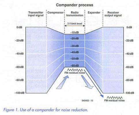
In order to solve this problem while keeping within the legal restrictions on frequency deviation, a compressor is built into the transmitter and an expander into the receiver. This technique is called a compander noise reduction system (Figure 1). 
The Dolby noise reduction system various the compression ratios with frequency. The compander noise reduction system used here, on the other hand, fixes the compression ratio at 2:1 over the entire frequency range, thus halving the dynamic range of the signal In the expander, whose ratio is set to 1:2, the exact opposite occurs, and the dynamic range is doubled again. A dynamic range of 100 dB is thus reduced to 50 dB for transmission.
We can now recalculate the frequency deviation required. With a residual noise of 50 Hz we need a frequency deviation of 500 Hz for a 20 dB dynamic range. 5 kHz for 40 dB, and 20 kHz for 52 dB. A wireless system with a signal-to-noise ratio of 50 dB can carry sound signals with an original dynamic range of 100 dB.
Why, in this ’digital age’, do we employ analogue transmission techniques for the wireless microphone rather than, for example, PCM? There are several reasons. Many countries have not allocated a dedicated frequency band for digital wireless microphones. Digital transmissions using PCM require a wide frequency band, which is not readily available below 1 GHz. Above 1 GHz ’dead spots’ start to appear, meaning that these frequencies are not suitable for live use where the performer may move around between various positions on stage. Finally, conversion to digital requires much more power, making it less practical to run the device from small batteries.
If desired, the modules (both receiver and transmitter) can be operated from a 1.5 V battery via a low-noise DC-DC converter available from Circuit Design. In order to achieve the 100 dB dynamic range that is possible with the wireless microphone, the noise produced by the DC-DC converter must be less than -60 dBm. The WA-DC-01 DC-DC converter requires an input voltage of at least 0.9 V and can produce an output voltage of 3 V at the maximum load current of 50 mA.
Reprinted Url Of This Article: http://www.seekic.com/blog/project_solutions/2011/08/19/Wireless_Microphone__Audio_in_the_ISM_band_1.html
Print this Page | Comments | Reading(2528)
Article Categories
New published articles
· Imagination works with TSMC to develop FinFET process
Author:Ecco Reading(33516)
· XMOS pushes event-driven MCUs with lower price
Author:Ecco Reading(3534)
· Intel brings upgraded 32-nm SoC for smartphones
Author:Ecco Reading(3250)
· Micron pushes TLC 128-Gbit NAND flash
Author:Ecco Reading(3816)
· Intel will stop supplying desktop motherboards
Author:Ecco Reading(5341)
· Processor market was expected to regain strength in 2013
Author:Ecco Reading(3318)
· It was reported that TSMC sales fall steeply
Author:Ecco Reading(3474)
· Cisco, NXP work with auto wireless startup
Author:Ecco Reading(3620)
· Micron was impacted by manufacturing glitch
Author:Ecco Reading(4017)
· China can make 22-nm transistor by themselves
Author:Ecco Reading(3819)
· Chip market rebound is coming, according to survey
Author:Ecco Reading(3760)
· Sony, Toshiba will spend more on chips, iSuppli reports
Author:Ecco Reading(3790)
· Qualcomm becomes the 13th company to join NFC Forum board
Author:Ecco Reading(6103)
· TSMC increases building work for FinFET fab
Author:Ecco Reading(3778)
· TI plans to cut 1,700 jobs in OMAP shift
Author:Ecco Reading(4587)