
Project Solutions
Playful Lights: Just there LEDs...
Published:2011/8/18 21:46:00 Author:Li xiao na From:SeekIC
By hubert Marwald
Here’s a recipe to make LEDs produce slow, continuous light effects rather than abrupt changes normally obtained from square-wave drive signals.
If you are after really accurate control of one or more LEDs, the best option by far is pulsewidth modulation (PWM) which is usually obtained from a dedicated PWM chip or a suitably programmed microcontroller. On the other hand, if the blink frequency not terribly important, other, much simpler methods are available. For example, get out two square-wave oscillators running at slightly different frequencies and mix their outputs together in an XOR (exclusive-OR) lo0c gate. That’s all it takes to build a beat-frequency oscillator whose low-frequency output signal may be pulse-width modulated in triangular(-ish) fashion.
Beat-frequency (BFO) or heterodyne oscillators are often used in metal detectors and in RF technology — you will rarely find one used in an audio frequency application. For example, if the first oscillator operates at 70 Hz and the second, at 70.1 Hz. connecting the two signals together in an XOR gate will produce a pulsewidth modulated triangular signal of just 0.1 Hz that is optically free from interference with 50-Hz (or 60-Hz) light sources.
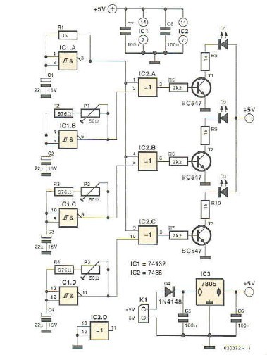
It takes just a few dead standard parts to take the principle of the BFO from theory to practice. If you would like to employ green and yellow LEDs for lighting purposes and gradually change the colors in a purposely erratic way, then a single IC type 74HCT132 does the job (Figure 1). 
Gate ICl.A forms the basic frequency generator that’s connected to all XOR gates. Each gate is complemented by an individual oscillator IC1.B, IC1.C and IC1.D whose oscillation frequency can be individually adjusted (with a preset) to a value very close to the basic frequency.
The XOR gates drive the LEDs by way of transistors whose collector resistors (R8, R9. RIO) need to be dimensioned in accordance with the required LED threshold voltage. the supply voltage and the brightness you’d like to achieve. In practice, the brightness changes are not quite triangular, not just because the rectangular oscillator signal does not have a 50vi duty cycle, but also as a result of the non-linear current/luminosity characteristics of the LEDs. 
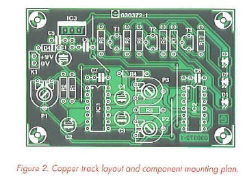
A PCB design is given (Figure 2) to enable all followers of the kitchen table series of mini projects to experiment to their hearts’ content. Sockets may be used for the two DIL ICs. With all parts fitted at the right polarity and properly soldered, the circuit should function straight away when K1 is connected to a 9-volt PP3 battery or a suitable mains adaptor.
Reprinted Url Of This Article: http://www.seekic.com/blog/project_solutions/2011/08/18/Playful_Lights__Just_there_LEDs.html
Print this Page | Comments | Reading(1615)
Article Categories
New published articles
· Imagination works with TSMC to develop FinFET process
Author:Ecco Reading(45489)
· XMOS pushes event-driven MCUs with lower price
Author:Ecco Reading(4141)
· Intel brings upgraded 32-nm SoC for smartphones
Author:Ecco Reading(3864)
· Micron pushes TLC 128-Gbit NAND flash
Author:Ecco Reading(4611)
· Intel will stop supplying desktop motherboards
Author:Ecco Reading(5961)
· Processor market was expected to regain strength in 2013
Author:Ecco Reading(3956)
· It was reported that TSMC sales fall steeply
Author:Ecco Reading(3619)
· Cisco, NXP work with auto wireless startup
Author:Ecco Reading(4282)
· Micron was impacted by manufacturing glitch
Author:Ecco Reading(4647)
· China can make 22-nm transistor by themselves
Author:Ecco Reading(4485)
· Chip market rebound is coming, according to survey
Author:Ecco Reading(4386)
· Sony, Toshiba will spend more on chips, iSuppli reports
Author:Ecco Reading(3953)
· Qualcomm becomes the 13th company to join NFC Forum board
Author:Ecco Reading(6795)
· TSMC increases building work for FinFET fab
Author:Ecco Reading(4467)
· TI plans to cut 1,700 jobs in OMAP shift
Author:Ecco Reading(5327)