
Project Solutions
REMOTE TEMPERATURE LOGGER FOR PIC 18F BOARD
Published:2011/8/16 2:03:00 Author:Phyllis From:SeekIC
Using a DS 1820 1-wire temperature sensor
By Peter Moreton
In this short article, we describe how to bit-bang a DSl8B20 or DSl8S20 temperature sensor device using PIC firmware written in ’C, and output the temperature values to the RS232 port, for logging on a PC, all using the PIC1 8Flash Development Board published last month.
The PIC18Flash development board described in Elektor Electronics January 2005 includes a header ’K8’ that delivers the appropriate processor pins for SPI / Microwire, I2C and 1-Wire communications to external devices. The SPI/Microwire and I2C protocols are supported by dedicated PIC hardware modules, and are quite easy to use as the hardware can be accessed using standard C18 library functions.
The Dallas/Maxim ’1-Wire’ bus does not benefit from a dedicated PIC hardware module and therefore must be implemented by ’bit-banging’ the appropriate MCU pin high and low in accordance with the 1-Wire protocol specification.
The 1-Wire bus
The Dallas / Maxim 1-Wire bus uses a single data line (hence ’1-Wire’) to transmit and receive data. Each 1-Wire device must also be connected to a common ground, and optionally to a power supply. If the power supply line is omitted, the 1-Wire device can be ’parasitically powered’ from the data line. The 1-Wire bus is normally held ’high’ using a 4k7 resistor to Vdd, and the devices pull the bus low and release the bus to go high, in order to signal data bits.
Pin RA4 of the PIC18F452 is particularly suited to the 1-wire protocol, as it is an open-drain pin, enabling the bus to be ’released’, and pulled high by the 4k7 bus pull-up.
The bus protocol works by defining a number of signal types: a reset pulse, presence pulse, write 0, write 1, read 0 and read 1. Each signal has timing parameters which must be strictly adhered to, and therefore an attribute of all 1-wire systems is the ability to generate accurate time-slots’. Readers wishing to fully understand 1-Wire signaling are referred to the in-depth documentation available from the Dallas/Maxim website.
DS18x20
Temperature Sensor
There are a number of similar devices in the DS1820 lineup; we have developed and tested PIC firmware for the DS18S20 giving 9-bits / 0.5 DegC resolution and the DS18B20 giving up to 12 bits/0.0625 DegC resolution. Both parts are accurate to within 0.5 DegC.
Either device may be used, by editing the DS1820.C source file appropriately to call one of the two available functions:
Celsius =
Read_Temperature_DS18S20 ( ); // use DS18S20 device
or
Celsius =
Read_Temperature_DS18B20 ( ); // use DS18B20 device
The pre-compiled HEX file included in the free download for this article (no. 040441-11.zip) assumes the higher resolution DS18B20 device is connected.
Circuit Description
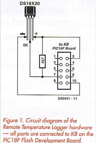
Figure 1 shows a Dallas DS18S20 or DS18B20 temperature sensor in a T092 package and a 4k7 pull-up resistor connected to the K8 header, as follows:
- K8 pin 2 to DS1820 pin 3, Vdd;
- K8 pin 10 to DS1820 pin 1, Ground;
- K8 pin 7 to DS1820 pin 2, DQ;
- Fit a 4k7 pull-up between DQ 
It is acceptable to extend the interconnecting cable up to several meters to allow for remote measurement, and we suggest that for external applications the DS1820 be protected from the elements using heatshrink tubing over a waterproof sealant.
Reprinted Url Of This Article: http://www.seekic.com/blog/project_solutions/2011/08/16/REMOTE_TEMPERATURE_LOGGER_FOR_PIC_18F_BOARD.html
Print this Page | Comments | Reading(2279)
Article Categories
New published articles
· Imagination works with TSMC to develop FinFET process
Author:Ecco Reading(33516)
· XMOS pushes event-driven MCUs with lower price
Author:Ecco Reading(3534)
· Intel brings upgraded 32-nm SoC for smartphones
Author:Ecco Reading(3250)
· Micron pushes TLC 128-Gbit NAND flash
Author:Ecco Reading(3816)
· Intel will stop supplying desktop motherboards
Author:Ecco Reading(5341)
· Processor market was expected to regain strength in 2013
Author:Ecco Reading(3318)
· It was reported that TSMC sales fall steeply
Author:Ecco Reading(3474)
· Cisco, NXP work with auto wireless startup
Author:Ecco Reading(3620)
· Micron was impacted by manufacturing glitch
Author:Ecco Reading(4017)
· China can make 22-nm transistor by themselves
Author:Ecco Reading(3819)
· Chip market rebound is coming, according to survey
Author:Ecco Reading(3760)
· Sony, Toshiba will spend more on chips, iSuppli reports
Author:Ecco Reading(3790)
· Qualcomm becomes the 13th company to join NFC Forum board
Author:Ecco Reading(6103)
· TSMC increases building work for FinFET fab
Author:Ecco Reading(3778)
· TI plans to cut 1,700 jobs in OMAP shift
Author:Ecco Reading(4587)