

Project Solutions
USB/I²C INTERFACE I-square-C rules… 2
Published:2011/8/15 22:09:00 Author:Amy From:SeekIC
Paul Goossens
Interface
The interface we’ve designed should satisfy several requirements. We would like to keep the installation under Windows as easy as possible. What’s more, it should be (relatively) easy to control the interface. It would also be nice if we could run longer cables between the interface and I2C modules, so the user can connect devices that are a long way away from the PC.
Our first task was to search for a suitable controller with a USB interface. We decided to use a TUSB3410 made by Texas Instruments, as this microcontroller has both a USB as well as an I2C interface. This is described (somewhat misleadingly) as a ’USB to Serial Port Controller’. In fact this is an 8051 compatible controller with a USB inter- face, 16 kBytes of program memory, an enhanced serial port and an I2C interface. All these goodies are contained within a small 32-pin SMD package. To satisfy the requirement for the I2C connection to work over greater distances, we have given the signals an extra boost with the help of a P82B715PNI2C bus extender.
Circuit diagram
The circuit diagram for our interface is shown in Figure 1. At the heart of the circuit is the TUSB3410 (IC1) with its associated oscillator (XI, C5 and C6). We’ve used an external mains adapter for the power supply. Its 9 V output is stabilized down to 5 V by IC4. There is also a requirement for a 3.3 V supply for the processor and the I2C EEPROM. For safety reasons we decided not to supply the circuit with power directly from the USB bus. The 5 V supply is also brought out on this connector and an overload or short could damage the USB interface in the PC. 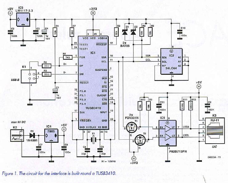
The data lines from the USB connector (Kl) are connected via resistors R2 and R3 to the appropriate data inputs of the controller. The D-f line is connected via a lk5 pull-up resistor to the PUR (Pull-Up Resistor) output of IC1. Normally this resistor is connected to the positive supply. This is required for a USB hub to detect that a full-speed USB device is connected to the USB port. By connecting this pull-up resistor to an output of the controller, the controller itself can tell the USB hub that a device is present. The reverse is also possible in that the controller can fool the hub that the device has been disconnected, by forcing this output low. This process is important during the booting of the chip (refer to the inset on booting the TUSB3410).
The firmware is stored in an I2C EEPROM (IC2) and is connected to the controller via the I2C bus. Diodes Dl and D2 absorb any potential voltage spikes and protect both I2C signal inputs of the controller. R5 are R6 the pull-up resistors that have to be present on every I2C bus.
You will have noticed that the I2C bus of the controller works at 3.3 V. These signals are not suitable for use in combination with a 5 V chip. Unfortunately, the PC bus-extender is a 5 V device, so both I2C signals first have to be converted to a 5 V level. This is taken care of by components Tl, T2, R9 and RIO. The P82B715PN I2C bus extender along with Rll and R12 allow longer cables to be connected to the I2C bus by lowering the impedance and increasing the current output. These signals are then taken to the outside world via K3.
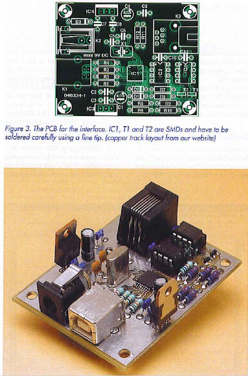
The double-sided PCB shown in Figure 3 is very small, but still has all the required connectors on board. Mounting the components shouldn’t be very difficult, with the exception of the SMDs: IC1, Tl andT2. It’s still possible to solder the two transistors using a soldering iron with a fine tip, but it becomes more difficult with the IC. The IC should first be fixed in the right place on the board with a drop of glue. Then solder all pins together as well as to the solder pads. You should work quickly to avoid the IC becoming too hot. After everything has cooled down again you should place a clean piece of desoldering braid across the pins and remove the excess solder (i.e. the shorts between the pins). Don’t attempt this with a solder sucker! Take care at all times that the IC doesn’t overheat. You should finally inspect all pins with a magnifying glass and multi-meter to check that they are connected properly and that there aren’t any shorts left.
Reprinted Url Of This Article: http://www.seekic.com/blog/project_solutions/2011/08/15/USB_Isup2;C_INTERFACE_I_square_C_rules…_2.html
Print this Page | Comments | Reading(2275)
Article Categories
New published articles
· Imagination works with TSMC to develop FinFET process
Author:Ecco Reading(31265)
· XMOS pushes event-driven MCUs with lower price
Author:Ecco Reading(3495)
· Intel brings upgraded 32-nm SoC for smartphones
Author:Ecco Reading(3213)
· Micron pushes TLC 128-Gbit NAND flash
Author:Ecco Reading(3722)
· Intel will stop supplying desktop motherboards
Author:Ecco Reading(5285)
· Processor market was expected to regain strength in 2013
Author:Ecco Reading(3283)
· It was reported that TSMC sales fall steeply
Author:Ecco Reading(3421)
· Cisco, NXP work with auto wireless startup
Author:Ecco Reading(3565)
· Micron was impacted by manufacturing glitch
Author:Ecco Reading(3971)
· China can make 22-nm transistor by themselves
Author:Ecco Reading(3756)
· Chip market rebound is coming, according to survey
Author:Ecco Reading(3713)
· Sony, Toshiba will spend more on chips, iSuppli reports
Author:Ecco Reading(3748)
· Qualcomm becomes the 13th company to join NFC Forum board
Author:Ecco Reading(6062)
· TSMC increases building work for FinFET fab
Author:Ecco Reading(3730)
· TI plans to cut 1,700 jobs in OMAP shift
Author:Ecco Reading(4514)