
Project Solutions
ROOM THERMOMETER (2)
Published:2011/8/11 1:33:00 Author:Phyllis From:SeekIC
By Gregor Kleine
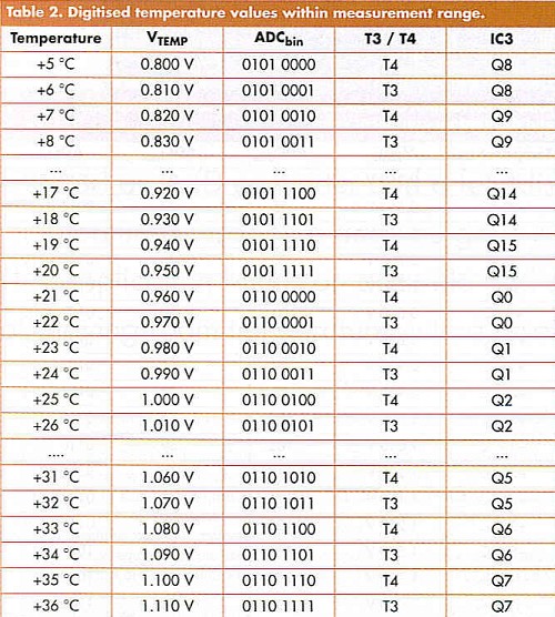
The sensor will be used at room temperatures so it is not necessary to display the complete temperature range. Table 1 shows that we only need to look at the least significant five bits at the output of the ADC if the displayed temperature range is limited from +5 "G (0101 0000) to +36 =C (0111 1111). The codes between these temperatures are not repeated. Table 2 lists the digital output values for temperatures within this range. 

Each degree is represented by a single LED so a total of 32 LEDs are required if a temperature range of 32 degrees is to be displayed. A 4 to 16 way decoder is used to decode bits Dl to D4 from the output f IC2. The least significant bit, DO, is used to switch either transistor T3 or T4, these drive two columns of eight LEDs. T4 is conducting when DO output is low while T3 conducts when DO is high. This arrangement effectively produces a 5 to 32-way decoder function. Only one of the green LEDs will be lit at any one time so current limiting on each column can be performed by a single resistor (R6 and R7).
Although the decoding is available to display a temperature range of 32 °C this can be reduced by simply omitting any LEDs that are not required. The circuit diagram shows just 15 LEDs fitted to display a range from +15 °C to +29 °C. Any other range can be chosen providing it falls within +5°C to 36°C.
Temperature sampling
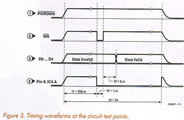
The MAX152 (IC2) 8-bit A-D converter operating from a +3 V supply is used to digitise the analogue output voltage from IC1. A logic low on the read input (RD, pin 8) and the chip select input (CS, pin 13) configures IC2 to standalone mode so that a pulse at the WR (pin 6) input will cause the converter to sample the analogue input voltage and output its digital value. The digital data is valid approximately 2 μs after the rising edge of the WR pulse. Figure 3 shows the timing diagrams corresponding to the numbered test points on the circuit.
Pressing SI switches power to the circuit and starts the temperature measuring process. The monoflop IC4.B supplies the WH pulse to the A/D converter but the start of this pulse is delayed (Tl = 500 [is) by C3 and R9 to allow the temperature sensor (IC1) to stabilize before its output is sampled. The WR pulse width (T2 = 1 fis) is governed by RIO and C2. The conversion time (T3) of IC2 is approximately 2 fvs so the output signals to the decoder (IC3) and transistors T3/T4 will be stable after a total time of T1+T2+T3 (503 /JS). This time period is so short that any LED that may incorrectly light during this period should go unnoticed. The trigger for monoflop IC4.A is also produced by the C3/R9 network during power-up and generates a 3-second pulse (pin 10) to switch transistor T2 and MOSFET Tl. The MOSFET is connected in parallel to SI so the pushbutton can be released and monoflop IC4.A ensures that the circuit will stay powered for about 3 seconds. 
Resistor R8 discharges the supply at the end of the timing period to ensure that the supply voltage falls to zero relatively quickly when the circuit switches off (Figure 3). At the end of the 3-second measurement period the inverting output of IC4. A (pin 9) will go high and residual charge in the supply is discharged through R8. This ensures that the circuit will be ready to take another temperature reading again relatively quickly after each measurement cycle is completed.
Reprinted Url Of This Article: http://www.seekic.com/blog/project_solutions/2011/08/11/ROOM_THERMOMETER__(2).html
Print this Page | Comments | Reading(719)
Article Categories
New published articles
· Imagination works with TSMC to develop FinFET process
Author:Ecco Reading(32820)
· XMOS pushes event-driven MCUs with lower price
Author:Ecco Reading(3526)
· Intel brings upgraded 32-nm SoC for smartphones
Author:Ecco Reading(3246)
· Micron pushes TLC 128-Gbit NAND flash
Author:Ecco Reading(3801)
· Intel will stop supplying desktop motherboards
Author:Ecco Reading(5331)
· Processor market was expected to regain strength in 2013
Author:Ecco Reading(3315)
· It was reported that TSMC sales fall steeply
Author:Ecco Reading(3462)
· Cisco, NXP work with auto wireless startup
Author:Ecco Reading(3604)
· Micron was impacted by manufacturing glitch
Author:Ecco Reading(4009)
· China can make 22-nm transistor by themselves
Author:Ecco Reading(3807)
· Chip market rebound is coming, according to survey
Author:Ecco Reading(3748)
· Sony, Toshiba will spend more on chips, iSuppli reports
Author:Ecco Reading(3780)
· Qualcomm becomes the 13th company to join NFC Forum board
Author:Ecco Reading(6094)
· TSMC increases building work for FinFET fab
Author:Ecco Reading(3764)
· TI plans to cut 1,700 jobs in OMAP shift
Author:Ecco Reading(4579)