
Project Solutions
ROOM THERMOMETER (1)
Published:2011/8/11 1:14:00 Author:Phyllis From:SeekIC
By Gregor Kleine
Just add an A/D converter and a few discrete LEDs to this temperature sensor chip and you get a simple thermometer. This application builds an accurate and stable thermometer displaying room temperature with a resolution of 1 °C.
The MAX6610 from MAXIM is a relative newcomer to the field of temperature sensing IC’s. The chip has a built-in voltage reference and an analogue output scaled to simplify integration with an 8 or 10-bit A/D converter (see textbox). A simple room thermometer does not usually require such precision and we run a risk of being accused of using a sledgehammer to crack a nut but the chip is quite versatile and this application provides a useful introduction to some of the features of the device. For more information on this device see the inset.
The complete room thermometer block diagram is shown in Figure 1. The MAX6610 precision temperature sensor outputs an analogue signal that’s linearly proportional to temperature. The signal is converted into a digital value by the 8-bit MAX152 analogue to digital (A/D) converter. Only five bits of the output byte are used by the decoder to light a single LED to indicate room temperature. Finally two monostables (monoflops) are used to generate all the timing signals necessary to control events in the circuit. The first produces the conversion signal to the A-D converter while the second controls a MOSFET in the power supply line to maintain power to the circuit during the measurement process. After an adjustable period it switches the thermometer off. It is only necessary to press SI briefly to activate the circuit and the temperature will be displayed for a few seconds. 
On closer inspection
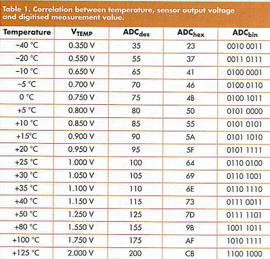
Figure 2 shows the complete circuit diagram of the room thermometer. IC1 contains the temperature sensing element and can be used in the temperature range from -40 °C to +125 "C. The sensor contains an on-board reference so that it does not require any calibration and is designed to interface with an analogue to digital (A-D) converter. It outputs a reference voltage of 2.560 V from pin 5. Pin 4 is the analogue TEMP output; the voltage level at this pin is proportional to temperature. If an 8-bit A-D converter is used to produce a digital value each single bit change corresponds to exactly 1: C temperature change. With a VREF of 2.560 V and an 8-bit A-D converter each bit change of the output is equal to an input change of 10 mV. IC1 produces an output signal with a characteristic of 10 mV/K with a DC offset of 0.750 V. The voltage V^g, is given by:
VTEMP = 750 mV + T x 10 mV
(with T in °C) 

Table 1 shows the output from an A-D converter represented as decimal (dec) hexadecimal (hex) and binary (bin) values.
Reprinted Url Of This Article: http://www.seekic.com/blog/project_solutions/2011/08/11/ROOM_THERMOMETER__(1).html
Print this Page | Comments | Reading(1665)
Article Categories
New published articles
· Imagination works with TSMC to develop FinFET process
Author:Ecco Reading(33516)
· XMOS pushes event-driven MCUs with lower price
Author:Ecco Reading(3534)
· Intel brings upgraded 32-nm SoC for smartphones
Author:Ecco Reading(3250)
· Micron pushes TLC 128-Gbit NAND flash
Author:Ecco Reading(3816)
· Intel will stop supplying desktop motherboards
Author:Ecco Reading(5341)
· Processor market was expected to regain strength in 2013
Author:Ecco Reading(3318)
· It was reported that TSMC sales fall steeply
Author:Ecco Reading(3474)
· Cisco, NXP work with auto wireless startup
Author:Ecco Reading(3620)
· Micron was impacted by manufacturing glitch
Author:Ecco Reading(4017)
· China can make 22-nm transistor by themselves
Author:Ecco Reading(3819)
· Chip market rebound is coming, according to survey
Author:Ecco Reading(3760)
· Sony, Toshiba will spend more on chips, iSuppli reports
Author:Ecco Reading(3790)
· Qualcomm becomes the 13th company to join NFC Forum board
Author:Ecco Reading(6103)
· TSMC increases building work for FinFET fab
Author:Ecco Reading(3778)
· TI plans to cut 1,700 jobs in OMAP shift
Author:Ecco Reading(4587)