
Project Solutions
USB EMBEDDED HOST CONTROLLER (4)
Published:2011/8/5 1:43:00 Author:Phyllis From:SeekIC
By Mark Schultz
Using the frameworks to read a USB Flash drive
Now it is time to create some application code that actually does something. At this point, we have created a driver and have a means to match it up to a device by class and subclass matching. Next up is to add code to the driver for its start and run functions.
When the driver starts, we want it to go out and interrogate the flash device to gather information about its file system. Then, the run function will be used to periodically check as to whether the user wants to read any file data. The driver’s start function will gather data about the file system in the following way:
-Perform a SCSI Inquiry command to get information on the attached device.
-Perform a SCSI Read Capacity command to get information about the size of the attached device.
-Perform a SCSI Read (l 0) with the LBA set to 0 to get data from the first physical sector on the flash device.
-Type cast the 16 bytes beginning at offset 1BE^ of the first sector to a partition record entry.
-Using the partition record information, locate the ’Start LBA’ — the number of the cluster containing the boot record.
-Perform a SCSI Read (10) with the LBA value set to the Start LBA to read the sector containing the boot record. Use the information in the boot record to fill in the volume information.
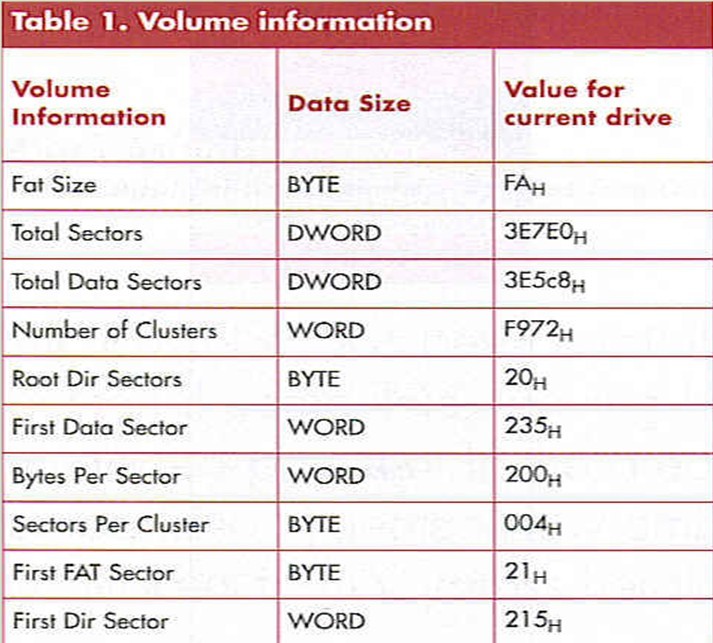
At this point, we have used three SCSI commands and our knowledge of the drive layout to obtain the information that was presented in Table 1. We can now use this information to read any file on the drive. 
The directory entry for a file will contain its Start Cluster number. This value will be passed to the file reading function in the Location field. The ReadFile function will read each sector in the cluster, and then check the FAT to see if there are additional clusters for the file. The code required to perform a file read is shown in Figure 4. 
The Sector value can be calculated using information contained in the Volume structure. Note that the file reading loop executes once for each sector in the cluster. When a cluster has been fully read, the FAT is checked to find the NexiCluster value. Also note the use of CBWs and CSWs for communicating with the drive.
Application Programming Interface
Figure 5 shows the hierarchy of the EZ-Host firmware. An external processor or application can communicate with the interface layer via RS232. Application code can be written to provide an API between the interface layer and the FindFile and ReadFile functions. 
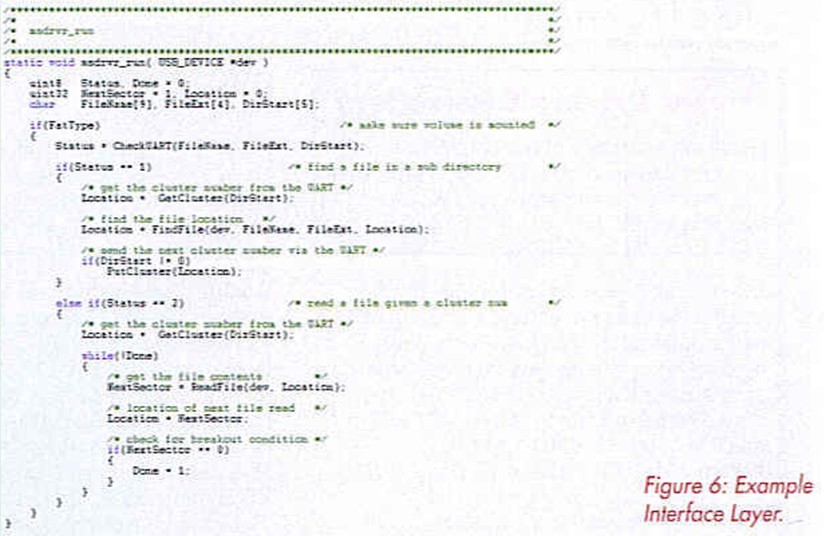
One possible interface layer is shown in Figure 6. Here, the UART is checked for a one byte Op Code followed by a filename, file extension and directory start location. An Op Code of ’1’ causes the FindFile function to be executed. An Op Code of ’2’ signifies a file read operation. 
The FileName and FileExt fields in the packet specify the file to be found or read. The additional packet field, DirStart allows for the location of files in either the root directory (DirStart = 0) or in a sub directory (DirStart = start cluster of the subdirectory).
As an example, suppose we wanted to read a file called fife] in the root directory:
The first UART Packet sent to the interface layer would have the parameter FileName set to File], a DirStart value of ’0’ and an Op Code of ’2’ for a file read. The EZ-Host firmware would return the contents of the file File I.
Now, suppose we wanted to read a file called File2 in the subdirectory SubDirl.
The first UART Packet would have the FileName parameter set to SubDirl, the Op Code set to ’1’ for file find and the DirStart value set to ’0’ The FindFile function will return the starting cluster of the SubDirl directory to the application. Next, another UART packet v/would be sent, this time with the FileName parameter set to File2, the Op Code set to ’2’ for file read and the DirStart value set to the starting cluster of SubDirl which was returned from the previous FindFile function. At this point, the EZ-Host will return the contents of File2.
Using this API and the above examples, a file from any directory on the drive can be read.
Conclusion
Using an embedded Host USB controller, removable mass storage can be added to any design. This feature allows for downloading of critical data or for firmware upgrades to the design via USB.
An embedded USB host may be implemented with just one additional IC and no third-party software. An embedded USB Host framework has taken care of all of the lower-level details for us. Cypress’ EZ-Host USB host can support the full speed Bulk transfers required to communicate with mass storage devices. The present code size is approximately 13 Kbytes. File system support can easily be added to support application specific devices.
Reprinted Url Of This Article: http://www.seekic.com/blog/project_solutions/2011/08/05/USB_EMBEDDED_HOST_CONTROLLER__(4).html
Print this Page | Comments | Reading(561)
Article Categories
New published articles
· Imagination works with TSMC to develop FinFET process
Author:Ecco Reading(33516)
· XMOS pushes event-driven MCUs with lower price
Author:Ecco Reading(3534)
· Intel brings upgraded 32-nm SoC for smartphones
Author:Ecco Reading(3250)
· Micron pushes TLC 128-Gbit NAND flash
Author:Ecco Reading(3816)
· Intel will stop supplying desktop motherboards
Author:Ecco Reading(5341)
· Processor market was expected to regain strength in 2013
Author:Ecco Reading(3318)
· It was reported that TSMC sales fall steeply
Author:Ecco Reading(3474)
· Cisco, NXP work with auto wireless startup
Author:Ecco Reading(3620)
· Micron was impacted by manufacturing glitch
Author:Ecco Reading(4017)
· China can make 22-nm transistor by themselves
Author:Ecco Reading(3819)
· Chip market rebound is coming, according to survey
Author:Ecco Reading(3760)
· Sony, Toshiba will spend more on chips, iSuppli reports
Author:Ecco Reading(3790)
· Qualcomm becomes the 13th company to join NFC Forum board
Author:Ecco Reading(6103)
· TSMC increases building work for FinFET fab
Author:Ecco Reading(3778)
· TI plans to cut 1,700 jobs in OMAP shift
Author:Ecco Reading(4587)