
Project Solutions
USB EMBEDDED HOST CONTROLLER (3)
Published:2011/8/5 1:21:00 Author:Phyllis From:SeekIC
By Mark Schultz
Framework Flow
The framework code will execute as follows. On power on reset, the EZ-Host microprocessor will initialize all registers and counters as well as all device structures. It will then enter a loop:
-Check the host USB ports for any changes in status (devices inserted or removed).
-Check the TD processor and get status of all TDs running on the two SIEs.
-Go through the list of active device drivers and execute the run function for each.
Checking the host USB port for status changes requires inspection of a change variable. The port change interrupt handler v/ill set this variable if a change occurs. If the port shows a change, enumeration code will be executed to service this change.
If a device is found, frameworks code will attempt to match the device to a registered driver. Driver matching can be accomplished in a number of ways. If there is only one specific device to be supported, the device’s VID and PID can be added to a ’Targeted Peripheral List’. The device’s VID and PID are then checked against this list. A more common method of device/driver matching is via device class and interface class. In the case of mass storage devices, both the device class and interface class have a value of ’8’ and their respective subclasses have a value of ’6.’ So, when the driver is created, these values will be entered into the appropriate fields (see Figure 3). 
Building an application
In this section we’ll show how to build a simple embedded USB design that controls a USB Flash drive. First, we will need to create a driver for the mass storage device. We can call the driver the mass_storage_driver or some name indicative of the capabilities of the device. The most important fields in this data structure are the class and subclass fields. The framework will use these values to match this driver up with any Flash device with the same class and subclass values. One other possibility here is to enter a specific Vendor ID and Product ID in the driver template. In this case, only the device containing those Vendor and Product IDs will be started when plugged in.
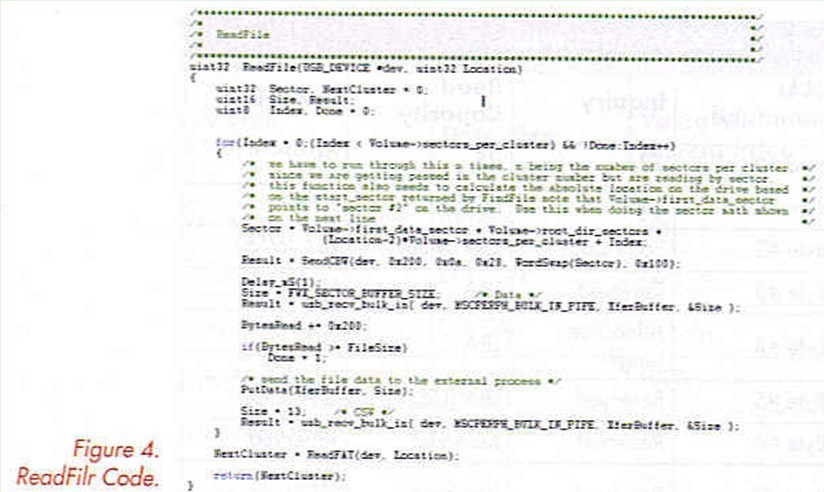
Once the driver is created, the next steps are to add the start, stop and run functions plus the class codes for the device so the driver can be found. A driver structure is shown in Figure 4. 
The name of the driver function has to be added to the file drvrlist.h:
#define FWX_DRIVER_LIST { &mass_storage_driver}
The mass_storage_driver’s ’start’ function will use the CBW/CSW protocol to interrogate the device to determine its characteristics. Code inside of these functions will get the data and pass it on to the application layer of the design. This will enable the higher-level layers of the application to handle the specifics of file management. The stop function will clean up any pending operations or transfers and notify the application layer that a device has been removed. The run function, finally, will be used to check for any incoming commands from the application code.
Reprinted Url Of This Article: http://www.seekic.com/blog/project_solutions/2011/08/05/USB_EMBEDDED_HOST_CONTROLLER__(3).html
Print this Page | Comments | Reading(341)
Article Categories
New published articles
· Imagination works with TSMC to develop FinFET process
Author:Ecco Reading(33516)
· XMOS pushes event-driven MCUs with lower price
Author:Ecco Reading(3534)
· Intel brings upgraded 32-nm SoC for smartphones
Author:Ecco Reading(3250)
· Micron pushes TLC 128-Gbit NAND flash
Author:Ecco Reading(3816)
· Intel will stop supplying desktop motherboards
Author:Ecco Reading(5341)
· Processor market was expected to regain strength in 2013
Author:Ecco Reading(3318)
· It was reported that TSMC sales fall steeply
Author:Ecco Reading(3474)
· Cisco, NXP work with auto wireless startup
Author:Ecco Reading(3620)
· Micron was impacted by manufacturing glitch
Author:Ecco Reading(4017)
· China can make 22-nm transistor by themselves
Author:Ecco Reading(3819)
· Chip market rebound is coming, according to survey
Author:Ecco Reading(3760)
· Sony, Toshiba will spend more on chips, iSuppli reports
Author:Ecco Reading(3790)
· Qualcomm becomes the 13th company to join NFC Forum board
Author:Ecco Reading(6103)
· TSMC increases building work for FinFET fab
Author:Ecco Reading(3778)
· TI plans to cut 1,700 jobs in OMAP shift
Author:Ecco Reading(4587)