
Project Solutions
Rolling Dice (3)
Published:2011/8/2 21:45:00 Author:Phyllis From:SeekIC
By Paul Goossens
Construction
The construction of the boards differs in a few ways from the usual method. In several places we have used standard components, which have to be surface mounted. The reason for this is that we’d rather not have any leads sticking out through the boards. This would result in a number of sharp points on the outside of the dice, which would damage your furniture when the dice is thrown, and this obviously isn’t our intention. To make things clear, we’ve included a series of photos of the construction of the prototype in Figure 3, as a picture is often worth a thousand words. 
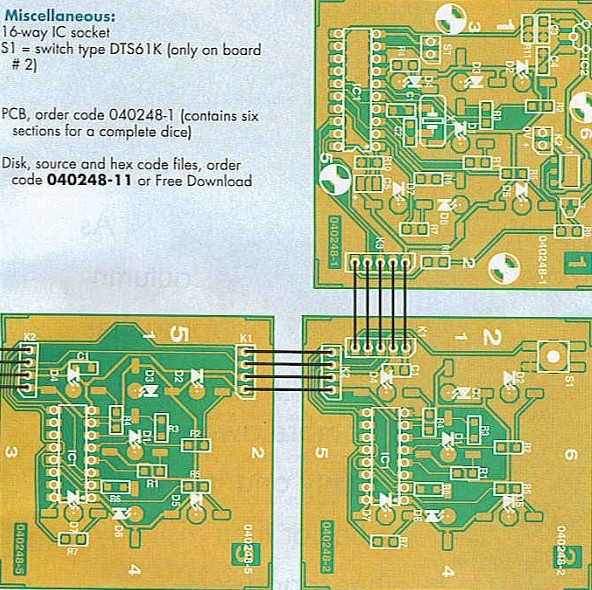
The component layouts for all boards are shown in Figure 4. First of all, the SMD components are soldered to the boards. Then it is the turn of the IC sockets, which also need to be surface mounted. You need to bend the pins outwards and cut them to length (take a measurement from the board first!). Next it’s the turn of the 42 (!) LEDs. The leads of the LEDs need to bent in the right form, as shown in Figure 5. Take great care that the anode and cathode are positioned correctly on the board. The case of the LED is then stuck through the hole. The ends of the leads should now be flat on the board, where they can be soldered. At this stage it is not important if the LEDs are not all at the same height. After soldering all LEDs they are pushed outwards such that they stick out just a little above the surface of the dice. If we now press the board onto the table, the LEDs should all be at the right height. 

Apart from the ICs in DIL packages, there are a few other components that have ’normal’ leads. As we don’t want the outside of the dice blighted by protruding leads and solder, these also have to be surface mounted. This includes the crystal and the mercury tilt-switch. The leads of these components have to be cut fairly short, and the ends turned through 90 degrees. These ends are then soldered onto the board. Take care that you don’t shorten the leads too much!
Connecting the boards
Once all boards have been populated it’s time to connect them together. Figure 4 shows how this is done. You should use individual pieces of wire for this, with a length of about 5 cm. If the wires are too short it makes it more difficult to fix the boards together at a later stage. There would also be a greater chance that one or more of the wires became loose!
Lastly the ICs are plugged into their sockets. (Make sure that you plug them in the right way round!) Now that the electrical construction is finished, the circuit should be tested. It is wise to do this before the dice has been fully assembled. At this stage the electronics are still easily accessible, should you need to make any repairs. After you have carefully checked for short circuits you can connect the 9 V battery. When you press the switch (on board 2), the circuit will come alive and a random number of LEDs lights up on the boards.
If you then shake board 1, the dice will simulate a roll. The numbers on all sides will change regularly. After a few seconds the changes slow down and the result of the roll is shown on the boards.
3D
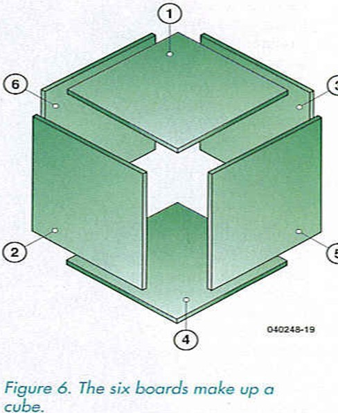
The electronics may now be completed, but it doesn’t look anything like a dice yet. The boards now have to be fixed together into a cube. Board number 4 is placed flat on the table and boards 2, 3, 5 and 6 are fixed at right angles to it (see Figure 6). 
Use a plastic angle section (available from most DIY stores) to fix the boards together. You should cut the angle section into small lengths and use these to glue the boards together.
You shouldn’t glue the last board (board 1), since this has to be removed every time the battery needs replacing. You need to glue a piece of angle section on the other boards, such that they line up with the 3 mm holes in board 1. Now carefully drill a 2.5 mm hole through each angle section at the point where it meets the mounting hole of board 1, then make a 3 mm thread in it. If you want a stronger thread you can glue a flat piece of plastic onto each angle section, which should be drilled and threaded as well. The inside of the dice should be filled with cotton wool or foam rubber, preventing the 9 V battery from moving or causing a short circuit. You can now screw board 1 into place.
And finally
You could give the dice a nice lick of paint, as we did with our prototype, but we leave that to your own preference. In any case, we hope that you enjoy constructing it and have fun using the dice in many games!
Reprinted Url Of This Article: http://www.seekic.com/blog/project_solutions/2011/08/02/Rolling_Dice__(3).html
Print this Page | Comments | Reading(510)
Article Categories
New published articles
· Imagination works with TSMC to develop FinFET process
Author:Ecco Reading(33516)
· XMOS pushes event-driven MCUs with lower price
Author:Ecco Reading(3534)
· Intel brings upgraded 32-nm SoC for smartphones
Author:Ecco Reading(3250)
· Micron pushes TLC 128-Gbit NAND flash
Author:Ecco Reading(3816)
· Intel will stop supplying desktop motherboards
Author:Ecco Reading(5341)
· Processor market was expected to regain strength in 2013
Author:Ecco Reading(3318)
· It was reported that TSMC sales fall steeply
Author:Ecco Reading(3474)
· Cisco, NXP work with auto wireless startup
Author:Ecco Reading(3620)
· Micron was impacted by manufacturing glitch
Author:Ecco Reading(4017)
· China can make 22-nm transistor by themselves
Author:Ecco Reading(3819)
· Chip market rebound is coming, according to survey
Author:Ecco Reading(3760)
· Sony, Toshiba will spend more on chips, iSuppli reports
Author:Ecco Reading(3790)
· Qualcomm becomes the 13th company to join NFC Forum board
Author:Ecco Reading(6103)
· TSMC increases building work for FinFET fab
Author:Ecco Reading(3778)
· TI plans to cut 1,700 jobs in OMAP shift
Author:Ecco Reading(4587)