
Project Solutions
Swiss Army knife (4)
Published:2011/8/1 21:21:00 Author:Phyllis From:SeekIC
By Jim Spence
Memory
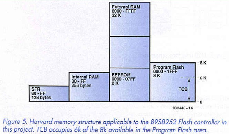
The memory space of the 8052 uses an architecture that shares parallel areas of memory. By logically combining the OE and PSEN signals to access the RAM it means that the external RAM can be used as program memory. The 8051 architecture is old and we’re sure that separating out the data and program memory seemed like a good idea at the time. This is what is known as Harvard Architecture and in theory at least it means that it is possible to fetch a code instruction at the same time as data in a single machine cycle.
Figure 5 shows the memory map and may cause some confusion for those of you who are more used to the conventional memory arrangements. The EEPROM space is pure data memory and assembler programs cannot run in this space, high level programs can. see later. There is provided 256 bytes of internal RAM that shares the upper half of this space with special function registers. The trick to ’getting at’ the various spaces lays in the instruction set. It would take up too much room here to go into detail but to give an example when accessing the code memory the MOVC instruction is used but when accessing external memory MOVX is used. Other techniques of direct and indirect addressing are used to access the internal RAM spaces. 
The on-board Flash memory contains TCB, version 1 and only occupies about the first 6 k. If this is good enough for your applications then you can forget all about the various memory addressing modes, TCB will take care of it.
Introduction to programming in TCB
The integer BASIC is a modified version of Tiny BASIC called Tiny Control Basic (TCB) that was designed specifically to enable users to get the maximum out of a microcontroller in the shortest possible time without having to go through a massive learning curve, or installing any special software.
The 8052 architecture has three memory spaces that are dealt with by TCB. Internal RAM, EEPROM and external RAM. These are accessed by the keywords IRAM, ROM & RAM respectively. Type IRAM and you should see this message:
i>iram
Internal Ram 00B4 to 00FF OK
i>
The ’i>’ prompt indicates that we are now in internal ram space. As you can see there are only a few bytes but this is good enough for a 2 or 3 line program. TCB will let you know if you run out of space. To access the EEPROM type ROM:
i>rom
Rom 0000 to 07FF
OK
e>
We are now in ROM space and as you can see there is 2 k of memory from 0000 to 07FF. At any time you can type ’DUMP’ to see the contents of the memory. The advantage of using this space is that it will retain the program even after power down. The disadvantage is that it is slower than RAM to write to and there is a limit to how many times you can write to it, approximately 100,000 times. In this project there is no external RAM so typing RAM will return an error. All TCB programs will be written to the EEPROM. TCB is capable of running a program at start up but it must begin with line 10. If line 10 does not exist any the program will effectively be erased. The start up procedure is as follows:
1. Check for input from user (space bar) - waits about 1 to 2 seconds
2. If no input, check ROM space for a program starting at line 10
3. Run it if it exists, if not check RAM space for a program starting at line 10 and run that.
If no line 10 exists and there is RAM it will erase (NEW command) the program in RAM and the sign on will be in RAM space. If there is no RAM then it will come up in internal RAM space (IRAM). Memory will not be erased if you press the space bar within one to two seconds of switch on. In this project of course there is no external RAM so the default will be to come up in internal RAM space "i>" unless there is a line 10 in ROM space in which case it will ran the program there.
If the space bar is pressed within approximately two seconds of reset or switch on, TCB will detect the Baud rate and come up in internal RAM space. TBC does not actually erase all of the RAM but simply puts the end of program marker (FE) into the first byte. You can verify this using the DUMP command after the NEW command. Referring to the MCU circuit, LED D3 is connected to port line P1.0 via two buffers in IC2. By default it will be off. This is because at start up all of the port lines are taken high.
To turn on the LED simply type: PZ1=254
i>pzl=254
OK
i>
PZl is the port 1 variable, anything you set this to will occur on port 1. By setting port 1 to 254 which is 11111110 in binary it will set pin 0 of port 1 to 0. By convention this pin is referred to as p 1.0
Try:
ROM
10 FOR J = 1 TO 10
20 PZ1=254
30 GOSUB 200
40 PZ1=255
50 GOSUB 200
60 NEXT J
70 END
200 FOR K = 1 TO 50
210 NEXT K
220 RETURN
The above should flash the LED on and off 20 times.
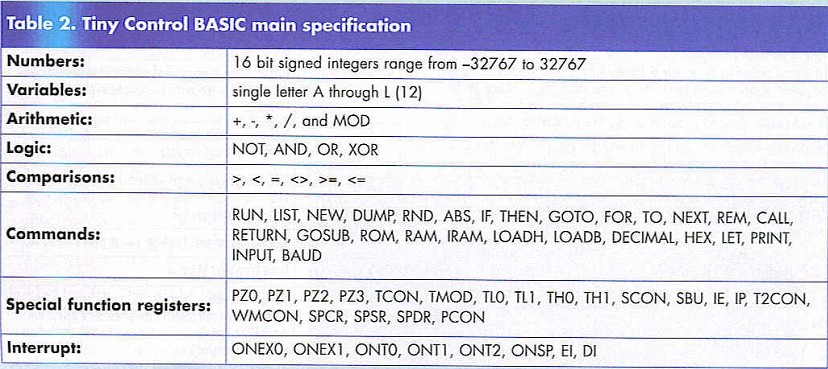
Table 2 gives a brief description of the language. 
Odds & ends
The massive amount of documentation Jim produced for this project would easily fill half this magazine, hence some items had to be moved to our website from where they can be downloaded free of charge. The items include the illustrated Quick Start Guide — Swiss Army Knife, the Tiny Control BASIC Manual and Simple Dice, so get downloading...
Reprinted Url Of This Article: http://www.seekic.com/blog/project_solutions/2011/08/01/Swiss_Army__(4).html
Print this Page | Comments | Reading(301)
Article Categories
New published articles
· Imagination works with TSMC to develop FinFET process
Author:Ecco Reading(33527)
· XMOS pushes event-driven MCUs with lower price
Author:Ecco Reading(3534)
· Intel brings upgraded 32-nm SoC for smartphones
Author:Ecco Reading(3250)
· Micron pushes TLC 128-Gbit NAND flash
Author:Ecco Reading(3816)
· Intel will stop supplying desktop motherboards
Author:Ecco Reading(5341)
· Processor market was expected to regain strength in 2013
Author:Ecco Reading(3318)
· It was reported that TSMC sales fall steeply
Author:Ecco Reading(3474)
· Cisco, NXP work with auto wireless startup
Author:Ecco Reading(3620)
· Micron was impacted by manufacturing glitch
Author:Ecco Reading(4017)
· China can make 22-nm transistor by themselves
Author:Ecco Reading(3820)
· Chip market rebound is coming, according to survey
Author:Ecco Reading(3761)
· Sony, Toshiba will spend more on chips, iSuppli reports
Author:Ecco Reading(3790)
· Qualcomm becomes the 13th company to join NFC Forum board
Author:Ecco Reading(6105)
· TSMC increases building work for FinFET fab
Author:Ecco Reading(3778)
· TI plans to cut 1,700 jobs in OMAP shift
Author:Ecco Reading(4587)