
Project Solutions
Swiss Army knife (1)
Published:2011/8/1 21:03:00 Author:Phyllis From:SeekIC
By Jim Spence
In a fix? Need to get a microcontroller project off the ground FAST? This article proves that an ultra-versatile microcontroller board can be built and programmed even by relative newcomers. The main circuit is based on the Atmel 89C8252 which has an 8052 architecture.
Knife
Tiny BASIC, 8051 assembler, RS232 and USB all in one project
Included is some very special (free) software that enables even the most code shy among you to make the controller do something. There are two alternatives to communicating with the circuit: USB 2.0 or RS232.
The original intention of the project was to produce a controller with built in BASIC that could retain the program after switch off, automatically start at switch on and not consist of too many chips. It should also be very easy to use and not require any special software on the PC. This has been achieved with more or less a single chip. This is possible because the 89C8252 has 2 kB of data EEPROM that can be programmed with high level instructions. The AT89C8252 micro was first used in the Elektor ’52 Flash Micro Board published in December 2001 and now a ’classic’ with PCB sales in the ’k’ range.
You may well be wondering why not use a BASIC or C compiler on your PC and blow the object code into the micro. These are good options, however you loose the immediacy of your actions. The Swiss Army Knife board immediately executes any code sent to it. Typing:
Pzl=0
at the console will immediately set all of the port 1 lines to Low. Also, a level of knowledge is required of the BASIC and C compilers before anything can be achieved. If you simply want to get on with your favourite robot project, then this is the way to do it. Mind you, you can still use the compilers or assembler later when you have done some experimenting.
RS232 and/or USB
Along the way the author got fed up with incorporating a dedicated communication system with every board especially when it was not usually needed in the final application. This lead to a separate power supply and RS232 connectivity that could be used with other circuits. However, as the RS232 format is getting a bit rusty and is not even included on some modern PCs it was considered nice to produce a USB interface as well and of course the USB can power the circuit. The result of the design effort is that you, the user, may choose between RS232 and USB when it comes to talking to the micro in your Swiss Army Knife. The Swiss Army Knife board consists of three sections: microcontroller (MCU), RS232 interface and USB interface. Each of these will be discussed separately below.
Microcontroller circuit
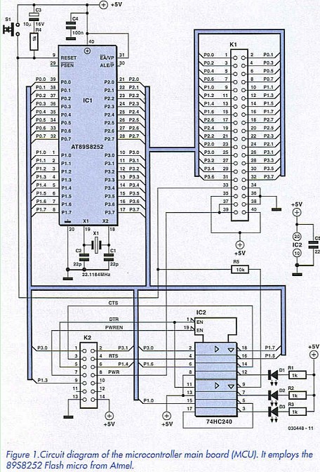
The MCU circuit shown in Figure 1 contains the popular AT89C8252 microcontroller clocked at 22.118 MHz and programmed with a version of Tiny Basic called Tiny Control Basic (TCB). The circuit shown is about as minimal as you can get. It is possible to program the code memory allowing a mix of high-level and assembler can be used. To facilitate this 1C2 has been included although the chip could be omitted in the finished application or if in-circuit programming is not required. Regarding connectors, Kl takes all of the I/O lines to a 40-way header and K2 is a 14-way header that mates with either of the two other boards. Pins 1 and 2 form the serial communication. The handshaking pins are not involved in the serial communication. 
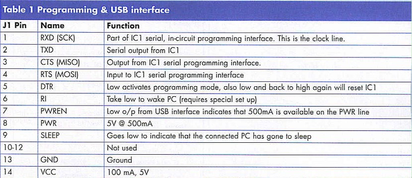
The AT89C8252 can be programmed serially using just three lines: SCK (clock), MfSO (output) and MOSI (input). Using these three lines and sending special bytes it is possible to get direct access to the code memory without removing the chip from the circuit, hence the term in-circuit programming. Pin 5 on Kl, the DTR line, initiates this process and the other pins are as described in Table 1. The DTR signal enables the top half of IC2, a tri-state inverting buffer. All of the lines are inverted by IC2 so the software must take this into account. The ByVac terminal described further on has suitable software built in. 
Along with the in-circuit programming there are various other signals available that apply to the USB interface. Pin 6 is the Ring Indicator. Providing the PC is set up correctly and the USB board is also configured correctly, this line can wake up a sleeping PC. By taking the line low the USB chip will send the correct signals to the PC to activate the PC from a suspended state. For this to work properly the microcontroller cannot be self powered, as the current available on standby is insufficient to operate the microcontroller without that also being in power down mode. In the power down mode the microcontroller will not be able to initiate a signal.
The USB specification has strict control over how much power can be taken from it and at what time. A normal USB is capable of providing a limited amount of current (100 mA) until it is properly configured. Once it is, up to 500 mA can be delivered by the USB bus. Pin 7 goes low to indicate that the USB is properly configured. This action enables the lower half of IC2 and as a result the PWR LED illuminates indicating that PWR is active and that current can be drawn from it. Power to external devices is taken from pin 8. The USB circuit (see later) will not provide any power to this pin until it is configured properly.
Pin 9 is a signal from the USB interface that goes low dining suspend. The user can monitor this line. Pin 14 is power provided from the USB bus, con-figured or not. This is only capable of supplying about 100mA when the bus is not configured. For this reason, external devices must use the PWR lines rather than Vcc.
By monitoring the above lines IC2 can be put into power down mode when the PC goes into the suspend state. RI Can be used to awaken the PC provided the USB and PC interfaces are set up correctly. To do this IC1 must also be self powered.
The P1.0 LED is connected via two inverters to the P1.0 I/O line of IC1, this can be used for anything. It is useful to have something there for testing purposes.
Reprinted Url Of This Article: http://www.seekic.com/blog/project_solutions/2011/08/01/Swiss_Army__(1).html
Print this Page | Comments | Reading(878)
Article Categories
New published articles
· Imagination works with TSMC to develop FinFET process
Author:Ecco Reading(33527)
· XMOS pushes event-driven MCUs with lower price
Author:Ecco Reading(3534)
· Intel brings upgraded 32-nm SoC for smartphones
Author:Ecco Reading(3250)
· Micron pushes TLC 128-Gbit NAND flash
Author:Ecco Reading(3816)
· Intel will stop supplying desktop motherboards
Author:Ecco Reading(5341)
· Processor market was expected to regain strength in 2013
Author:Ecco Reading(3318)
· It was reported that TSMC sales fall steeply
Author:Ecco Reading(3474)
· Cisco, NXP work with auto wireless startup
Author:Ecco Reading(3620)
· Micron was impacted by manufacturing glitch
Author:Ecco Reading(4017)
· China can make 22-nm transistor by themselves
Author:Ecco Reading(3821)
· Chip market rebound is coming, according to survey
Author:Ecco Reading(3761)
· Sony, Toshiba will spend more on chips, iSuppli reports
Author:Ecco Reading(3790)
· Qualcomm becomes the 13th company to join NFC Forum board
Author:Ecco Reading(6106)
· TSMC increases building work for FinFET fab
Author:Ecco Reading(3778)
· TI plans to cut 1,700 jobs in OMAP shift
Author:Ecco Reading(4587)