
Project Solutions
Electronic Valentine Heart: LEDs are red my dear(2)
Published:2011/7/31 22:12:00 Author:Li xiao na From:SeekIC
Design by F. Wolling
Circuit and component calculations
As most of you will know, there are few, if any, applications of LEDs that do not include some form of current limiting resistor. After all, LEDs are simply diodes that light when a forward bias voltage is applied across them. They also ’exhibit’ the typical diode characteristic shown in Figure 1. If you apply a slowly rising voltage starting at 0 V to a LED, such that the device conducts (+ to anode; -to cathode), you will notice that nothing happens for quite a while — no current appears to flow. However, once the voltage exceeds a critical level, current starts to flow, rising very quickly when the voltage is increased further. This so-called threshold voltage occurs at 0.6 V with normal silicon diodes and at 1.6 V with most LEDs (as in Figure 1). A value of 1.7 V will be noted when testing low-current LDs in this way. Without a current limiting resistor, a small increase of the voltage beyond the threshold voltage would mean imminent destruction of the LED because the forward current rises extremely fast and soon exceeds the ’safe’ level. 
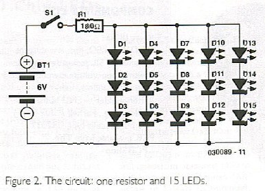
With a resistor in series with the LED, things look different because according to Ohm’s law, the resistor becomes the main current determining factor. In the circuit of the Electronic Valentine Heart (Figure 2) five strings of series-connected LEDs are connected in parallel. Each string consists of three LEDs. The voltage across each of these strings equals three times the forward conducting voltage of a single LED. Assuming a device voltage of 1.7 V we get 
3 x 1.7 V = 5.1 V
The LEDs are connected to the battery by way of a 180Ω resistor. Although the battery voltage is 6 V nominally (2x3 V), we should use the value 5.9 V to account for the load on button cells. If the voltage across the LED strings is 5.1 V, the resistor is accountable for the voltage difference between the two voltages at its terminals. The difference works out at 5.9 V - 5.1 V = 0.8 V. From this value we can calculate the current as
0.8 V / 180Ω = 0.00444 A = 4.44 mA
This current is supplied by the battery, flowing through the resistor and the LEDs. Because all LEDs are of the same type and the voltage across each string is also equal, it is safe to assume that the current is equally divided across the five LED strings. Hence, the current through each individual LED equals
4.44 mA / 5 = 0.89 mA
Not a lot, you may think, but sufficient for a low-current LED to light with reasonable brightness. If the circuit was modified such that all LEDs are connected in parallel, the current consumption from the battery would be three times as high (assuming the same LED current is maintained). The load on the battery would then become about 13 mA, which is rather heavy on the button cells used. Besides, the difference in brightness between individual LEDs would be far more noticeable than with the series-connected version.
If you would like to know more about LEDs and how they can be used in large clusters, you should get a copy of our article ’LED Arrays’ from the April 2003 issue of Elektor Electronics. The Internet is also a good source for additional information on LED calculations, see ’Web Pointers’ at the end of this article.
Reprinted Url Of This Article: http://www.seekic.com/blog/project_solutions/2011/07/31/Electronic_Valentine_Heart__LEDs_are_red_my_dear(2).html
Print this Page | Comments | Reading(584)
Article Categories
New published articles
· Imagination works with TSMC to develop FinFET process
Author:Ecco Reading(33527)
· XMOS pushes event-driven MCUs with lower price
Author:Ecco Reading(3534)
· Intel brings upgraded 32-nm SoC for smartphones
Author:Ecco Reading(3250)
· Micron pushes TLC 128-Gbit NAND flash
Author:Ecco Reading(3816)
· Intel will stop supplying desktop motherboards
Author:Ecco Reading(5341)
· Processor market was expected to regain strength in 2013
Author:Ecco Reading(3318)
· It was reported that TSMC sales fall steeply
Author:Ecco Reading(3474)
· Cisco, NXP work with auto wireless startup
Author:Ecco Reading(3620)
· Micron was impacted by manufacturing glitch
Author:Ecco Reading(4017)
· China can make 22-nm transistor by themselves
Author:Ecco Reading(3820)
· Chip market rebound is coming, according to survey
Author:Ecco Reading(3761)
· Sony, Toshiba will spend more on chips, iSuppli reports
Author:Ecco Reading(3790)
· Qualcomm becomes the 13th company to join NFC Forum board
Author:Ecco Reading(6105)
· TSMC increases building work for FinFET fab
Author:Ecco Reading(3778)
· TI plans to cut 1,700 jobs in OMAP shift
Author:Ecco Reading(4587)