
Project Solutions
iAccess--an intelligent access control system (4)
Published:2011/7/28 1:17:00 Author:Li xiao na From:SeekIC
Design by I. Joostens
Construction, alignment and commissioning
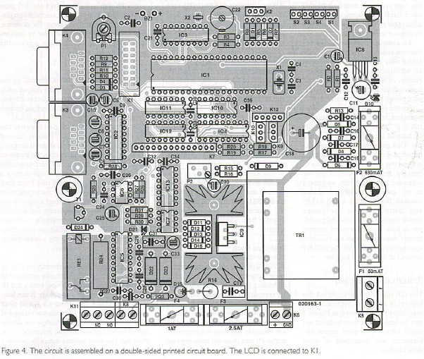
The circuit is built on a double-sided printed circuit board with plated-through holes, which is illustrated in Figure 4. Despite the complexity of the schematic diagram, assembling the board should not present any significant problems. Use IC sockets for all ICs and check that the values and polarities of the components are correct before soldering them in place, since it can be difficult to unsolder components from a circuit board with plated-through holes. 
After assembling the board, do not immediately fit the ICs in their sockets, and leave the LCD disconnected for the time being.
Turn P2 fully to the left and connect K5 to the mains. Using P2, adjust the voltage on K6 (the connector for the lead-acid battery) to exactly 13.8 V. Then check the 5-V supply voltage at pins 1 and 2 of Kl and at each of the IC sockets, except for IC4 and IC5 (which receive 13.8 V).
Switch off the mains voltage and rotate C22 so the plates of the capacitor are half engaged. Set PI to its mid-range position.
Now insert all ICs into their sockets and connect the LCD to Kl using a length of 16-way flat cable. Switch the mains voltage on again. At this stage, it is quite normal for the circuit to not do anything, since the firmware is missing.
Using a standard 1:1 serial cable, connect the programming port (K4) to a free serial port on a computer. Unzip the Zip file containing the firmware and put all the files in a folder on the hard disk. Start the program MicroFlash.exe, which is located in the folder with the firmware, and select the proper COM port. Click on ’Flash hex’ and select file ’iacc-v35.hex’ or equivalent (depending on the version number). The microcontroller will now be programmed. Depending on the speed of your computer, this may take a few minutes. As soon as the programming is finished, the microcontroller will be reset and the main program will start to execute in Run mode. Normally, buzzer BZI should emit a short beep at this time.
Using PI, adjust the contrast of the LCD. If everything has gone well, the following text will now appear on the LCD: ’iACCESS 3.5 Mo 00:00’, ’Run...’
Allow the entire circuit to warm up for 15 minutes, and then use P2 to again adjust the voltage on K6 to 13.8 V as precisely as you can.
If you have a frequency meter, you can connect it between ground and pin 11 of IC3. You can then adjust C22 so the signal has a period of 7.8125 ms (128 Hz). If you don’t have a frequency meter, you can adjust C22 by feel’, depending on whether the clock runs fast or slow. Even without any adjustment, the clock is quite accurate.
After fitting the circuit board into a suitable enclosure, you should attach an identification label, as illustrated in Figure 3. As this is a mains-powered device, this is obligatory in connection with electrical safety.
Reprinted Url Of This Article: http://www.seekic.com/blog/project_solutions/2011/07/28/iAccess__an_intelligent_access_control_system_(4).html
Print this Page | Comments | Reading(305)
Article Categories
New published articles
· Imagination works with TSMC to develop FinFET process
Author:Ecco Reading(33527)
· XMOS pushes event-driven MCUs with lower price
Author:Ecco Reading(3534)
· Intel brings upgraded 32-nm SoC for smartphones
Author:Ecco Reading(3250)
· Micron pushes TLC 128-Gbit NAND flash
Author:Ecco Reading(3816)
· Intel will stop supplying desktop motherboards
Author:Ecco Reading(5341)
· Processor market was expected to regain strength in 2013
Author:Ecco Reading(3318)
· It was reported that TSMC sales fall steeply
Author:Ecco Reading(3474)
· Cisco, NXP work with auto wireless startup
Author:Ecco Reading(3620)
· Micron was impacted by manufacturing glitch
Author:Ecco Reading(4017)
· China can make 22-nm transistor by themselves
Author:Ecco Reading(3820)
· Chip market rebound is coming, according to survey
Author:Ecco Reading(3761)
· Sony, Toshiba will spend more on chips, iSuppli reports
Author:Ecco Reading(3790)
· Qualcomm becomes the 13th company to join NFC Forum board
Author:Ecco Reading(6105)
· TSMC increases building work for FinFET fab
Author:Ecco Reading(3778)
· TI plans to cut 1,700 jobs in OMAP shift
Author:Ecco Reading(4587)