
Project Solutions
VHF-Low Explorer (2)
Published:2011/7/28 20:47:00 Author:Phyllis From:SeekIC
By Gert Barrs
What’s in it for me
While the radio amateur fraternity is poised to grab their share of the spectrum around 70 MHz, it should be noted that the 68-88 MHz band has other, equally interesting users and applications including Government, MoD and PMR {private mobile radio) communications (not encrypted in many cases), security services, telemetry and the odd TV station. Unless you live in a really remote place, even a simple antenna in your loft will bring in a surprising number of stations using the 4-m band. Tune and Explore!
Design considerations
From the very start of this project, the design was to remain as simple as possible. This decision has important consequences as well as a background we’d like to share with you. Sure, a receiver for the 68-88 MHz band could be a double-conversion superheterodyne design employing a 10.7-MHz filter, a 10-turn pot for the tuning and a final intermediate frequency (IF) bandwidth of 15 kHz to suit NBFM (narrow-band frequency modulated) signals picked up at a sensitivity of 1 /JV or so, not forgetting a squelch to make sure the receiver is quiet when nothing is received. Great shopping list, but such a receiver will be expensive as well as difficult to adjust by beginners. Next, please!
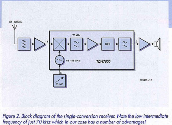
The good news is that an attractive alternative is available in the form of the TDA7000 chip from Philips that’s been around for more than 10 years now, which is quite remarkable for a consumer-market chip. This ’evergreen’, then, contains a complete radio receiver with a very low IF of just 70 kHz. Okay, so image frequencies occur just 2 x 70 kHz = 140 kHz away from the desired signals, but that need not be a problem because on the positive side we do not have to worry too much about the input filtering. Also, the IF filters responsible for the selectivity may be realized as a simple R-C network, obviating the need for expensive and esoteric quaitz or ceramic filters.
Block diagram 
Even if you are not a radio boffin, the block diagram of the proposed receiver in Figure 2 should be largely self-explanatory. The TDA7000 contains a muting circuit which is activated at a level of about 6 /vV. As we will want to use a whip antenna as the bare minimum, an RF preamplifier will have to be inserted between the antenna and the input of the TDA7000. Everything from the output of the RF preamp right up to the input of the audio amplifier is contained in the TDA7000. If you want to know everything about the chip, get a copy of the datasheet (see Web pointers)
Reprinted Url Of This Article: http://www.seekic.com/blog/project_solutions/2011/07/28/VHF_Low_Explorer__(2).html
Print this Page | Comments | Reading(1413)
Article Categories
New published articles
· Imagination works with TSMC to develop FinFET process
Author:Ecco Reading(33527)
· XMOS pushes event-driven MCUs with lower price
Author:Ecco Reading(3534)
· Intel brings upgraded 32-nm SoC for smartphones
Author:Ecco Reading(3250)
· Micron pushes TLC 128-Gbit NAND flash
Author:Ecco Reading(3816)
· Intel will stop supplying desktop motherboards
Author:Ecco Reading(5341)
· Processor market was expected to regain strength in 2013
Author:Ecco Reading(3318)
· It was reported that TSMC sales fall steeply
Author:Ecco Reading(3474)
· Cisco, NXP work with auto wireless startup
Author:Ecco Reading(3620)
· Micron was impacted by manufacturing glitch
Author:Ecco Reading(4017)
· China can make 22-nm transistor by themselves
Author:Ecco Reading(3820)
· Chip market rebound is coming, according to survey
Author:Ecco Reading(3761)
· Sony, Toshiba will spend more on chips, iSuppli reports
Author:Ecco Reading(3790)
· Qualcomm becomes the 13th company to join NFC Forum board
Author:Ecco Reading(6105)
· TSMC increases building work for FinFET fab
Author:Ecco Reading(3778)
· TI plans to cut 1,700 jobs in OMAP shift
Author:Ecco Reading(4587)