
Project Solutions
Sensors Go Systematic (2)
Published:2011/7/28 2:25:00 Author:Amy From:SeekIC
By Helmuth Lemme
Signal conditioning
Amplifying the signal is not the only task of signal conditioning. .Many of the physical effects utilised for sensors are temperature dependent. To compensate for this, a temperature sensor that suitably adjusts the gain can be incorporated into the system. In many cases, the transfer characteristics are non-linear and must be linearised. This is especially true for conventional temperature sensors, such as NTC and platinum resistors, as well as thermocouples.
Regardless of whether linearisation is performed using conventional analogue electronics or software in the signal evaluation computer, it always requires additional effort and expense. If a silicon-based temperature sensor is available, it can be housed on the same chip and the linearisation can be implemented directly adjacent to the sensor. Such components are now in widespread use. One example is the National Semiconductor LM35, which has been manufactured for many years already. It generates an output signal that precisely and linearly increases with temperature at the rate of 10 mV/K. Over the years, it has been joined by a whole group of relatives that operate in similar manner (for more information. see www.national.com/appinfo/tempsensors/products.html).
Sensor/controller combos
Once a sensor has already become an IC, the next step is to integrate functions that were previously wired externally in the form of ’discrete’ circuits. An example of such functions is comparators driving outputs that switch if the temperature crosses a certain threshold temperature. The threshold values can be provided externally in analogue or digital form. Integrated A/D converters are also commonly present, usually with serial output in order to save pins. The next logical step is to add a microcontroller to the chip. This makes a multitude of additional functions possible, including externally programmable parameters such as sensitivity and measurement range, calibration, and many others. An EEPROM (also on the chip) can store the calibration data. In this way, the sensor is transformed into a miniature computer.
A significant advantage of such ’intelligent’ sensors is reduced type diversity. Instead of making a large variety of types that differ only in their detailed specifications, manufacturers can make just a few basic types, which can then be produced in much larger quantities. The parameters required for operational use are entered by the user, and in many cases they can also be subsequently modified.
A typical example of this type of sensor is the family of Hall sensors made by Micronas. The first model of this family was the HALSOO, which was further refined to yield the derivative types HAL805. HAL810 and HALS15 (www.micronas.com/products/overvievv/sensors/index.php)
In this case, processing the measurement signal is especially difficult. The signal voltage from the Hall element is extremely small, and it is superimposed on a large offset voltage. In addition, both voltages are highly temperature dependent. Temperature compensation requires complex circuitry, and optimum results can only be achieved using a switching technique, similar to a chopper amplifier.
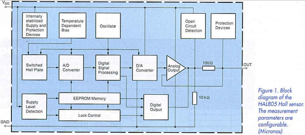
With these sensors, users can configure a whole range of parameters according to their wishes: sensitivity, the upper and lower limits of the measurement range, measurement bandwidth and the amount of temperature compensation. A special feature here is that the temperature dependence can either be entirely eliminated (even including its nonlineariry. for which purpose a quadratic correction network in included), or a certain proportion of the temperature dependence can be intentionally retained. This can be useful if (for instance) the sensor is used with a magnet that has its own temperature dependence. In this way, the temperature dependence of the overall system (and thus the temperature dependence of the switching distance, for example) can be reduced to nearly zero.
In normal measurement operation, this sensor is operated from a 5-V supply voltage and generates an analogue signal that is proportional to the local magnetic flux density. It can be programmed by increasing the supply voltage to a higher level and modulating the voltage. A voltage in the range of 5.6-6 V corresponds to a logic Low level, while the range of 6.8-8.5 V corresponds to a High level. The data are written serially. In this mode the sensor output operates digitally, and the internally stored parameter values can be requested and read out serially via the output. The sensor is electronically "sealed" on conclusion of the programming process, and subsequent programming is no longer possible. The output signal is again analogue after programming. 
This approach allows the number of leads to be kept to an absolute minimum: ground, supply voltage and output. This keeps down the cost, which essentially depends on the package type used and thus the number of leads. The packaged sensor, with dimensions of 4 x 4 x 1.5 mm, looks like a plastic-cased transistor. Its block diagram is shown in Figure 1.
Reprinted Url Of This Article: http://www.seekic.com/blog/project_solutions/2011/07/28/Sensors_Go_Systematic_(2).html
Print this Page | Comments | Reading(320)
Article Categories
New published articles
· Imagination works with TSMC to develop FinFET process
Author:Ecco Reading(45489)
· XMOS pushes event-driven MCUs with lower price
Author:Ecco Reading(4141)
· Intel brings upgraded 32-nm SoC for smartphones
Author:Ecco Reading(3865)
· Micron pushes TLC 128-Gbit NAND flash
Author:Ecco Reading(4611)
· Intel will stop supplying desktop motherboards
Author:Ecco Reading(5961)
· Processor market was expected to regain strength in 2013
Author:Ecco Reading(3956)
· It was reported that TSMC sales fall steeply
Author:Ecco Reading(3619)
· Cisco, NXP work with auto wireless startup
Author:Ecco Reading(4282)
· Micron was impacted by manufacturing glitch
Author:Ecco Reading(4647)
· China can make 22-nm transistor by themselves
Author:Ecco Reading(4485)
· Chip market rebound is coming, according to survey
Author:Ecco Reading(4386)
· Sony, Toshiba will spend more on chips, iSuppli reports
Author:Ecco Reading(3953)
· Qualcomm becomes the 13th company to join NFC Forum board
Author:Ecco Reading(6795)
· TSMC increases building work for FinFET fab
Author:Ecco Reading(4467)
· TI plans to cut 1,700 jobs in OMAP shift
Author:Ecco Reading(5327)