
Project Solutions
Drop-in Microcontroller Board (2)
Published:2011/7/27 21:35:00 Author:Phyllis From:SeekIC
Hardware
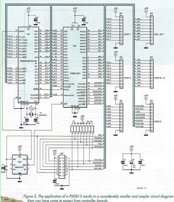
The starting point for your experiments with this chip is a piece of hardware we developed that could be ’dropped’ into several circuits. The circuit diagram of the drop-in module may be found in Figure 2. Even a cursory glance at the drawing should convince you that simplicity is trumps. Thanks to the multifunctional character of the PSD813 chip, this bit of hardware may be used in combination with a microcontroller in many different application circuits. What’s more, the JTAG interface makes the total configuration great for use as an experimental or development system. 
For the heart of the circuit we went for a DS80C320 (IC1). This is an 80C32 compatible micro that’s much faster than the ordinary 80C32, hence will not let easily let you down in regard of processing speed. Its main pins are all connected to the PSD813F in position IC2. Furthermore, the circuit contains a microprocessor supervisor circuit built around IC3 and SI, some components to complete the clock oscillator and a handful of small caps to clean and buffer the supply voltage.
An on-board power supply is not provided because this module will typically act as an add-on to an existing circuit supplying +5 V, rather than a stand-alone unit. We did, however, bond out all relevant signals to pins on connectors Kl through K6. Connector K7 is the JTAG interface that allows the chip to be programmed. This interface has been described several times already in this magazine. 
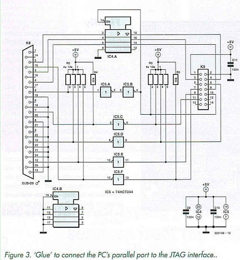
A suitable interface to connect the parallel port to the JTAG interface is shown in Figure 3. This programmer is directly accessible from the associated program called PSDSoft and that is why we believe it’s really indispensable. The programmer is connected to the PC’s parallel port via K8 and a cable with 1-to-l pin correspondence. K9 is the JTAG port — this is connected to the plug-in module via a 14-way flatcable. IC5 affords buffering and inverting of the signals. The enable input is controlled by the PC, ensuring that the relevant signals do not load the circuit connected when in the ’off state.
Reprinted Url Of This Article: http://www.seekic.com/blog/project_solutions/2011/07/27/Drop_in_Microcontroller_Board__(2).html
Print this Page | Comments | Reading(2593)
Article Categories
New published articles
· Imagination works with TSMC to develop FinFET process
Author:Ecco Reading(32821)
· XMOS pushes event-driven MCUs with lower price
Author:Ecco Reading(3526)
· Intel brings upgraded 32-nm SoC for smartphones
Author:Ecco Reading(3246)
· Micron pushes TLC 128-Gbit NAND flash
Author:Ecco Reading(3801)
· Intel will stop supplying desktop motherboards
Author:Ecco Reading(5331)
· Processor market was expected to regain strength in 2013
Author:Ecco Reading(3315)
· It was reported that TSMC sales fall steeply
Author:Ecco Reading(3462)
· Cisco, NXP work with auto wireless startup
Author:Ecco Reading(3604)
· Micron was impacted by manufacturing glitch
Author:Ecco Reading(4009)
· China can make 22-nm transistor by themselves
Author:Ecco Reading(3807)
· Chip market rebound is coming, according to survey
Author:Ecco Reading(3748)
· Sony, Toshiba will spend more on chips, iSuppli reports
Author:Ecco Reading(3780)
· Qualcomm becomes the 13th company to join NFC Forum board
Author:Ecco Reading(6094)
· TSMC increases building work for FinFET fab
Author:Ecco Reading(3764)
· TI plans to cut 1,700 jobs in OMAP shift
Author:Ecco Reading(4579)